Lance is headed for the finish line in terms of completing the transformation from his origin as a 2016 Kenworth T270 Horton Ambulance to our awemazing eXpedition Recreation Vehicle XRV aka “Lance”. He and I are now back up at our place on Saturna Island where I have a great woodworking workshop that I am thoroughly enjoying as I complete the last phase of the internal buildout of the original Horton 14 x 8 ft ambulance box. This is the only wood I’ve used so far as everything else is either extruded aluminium or XAL, Aluminium Composite Material ACM for the surfaces of the walls and ceiling and then LVT solid vinyl planks for the floor and solid surface acrylic for the countertops.
No surprise to those of you who have been following my adventures for any time, the lead up to this post is a great story and the wood itself has its own which I’ll outline first.
Mother Nature + Friends Converge
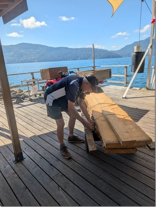
I have some dear friends, Rick & Sherry and we lived and worked together when Rick & I were teachers on the Canadian Armed Forces jet fighter base in Baden Baden Germany in the early 80’s. Hard to believe that is now more than 45 years ago! Rick and Sherry live in Vancouver and have had a lovely property I’ve been to many times over the years on Gambier Island off the coast of North Vancouver as you’re driving up to Whistler mountain. Their son Colin was just a young boy when we were all together in Baden and has grown a wee bit since then. On our way back from our “sea trials” with Lance last summer when we drove across the US to attend the wedding of my niece in Portland Maine and then back across Canada, we stopped in to see Rick, Sherry and Colin while they were at their place on Gambier Island. We stayed overnight swapping stories and catching up. In the course of our conversations they told me about a very large old Cherry tree, over 200 years old they think, that had come down in a big wind storm a few years ago. Colin lives on Gambier full time which is saying something as it is totally off grid and only accessible by private boat, so he grows all his own food and is very talented and self sufficient young man. Over the years, he and I have developed a growing friendship discussing some of our respective DIY projects and he has been following my progress in transforming Lance into an XRV. In telling the stories about the stories about this big old tree coming own, Colin told how he had salvaged as much as he could using a chain saw milling machine he had assembled and he was anxious to show me the planks from his handiwork. As we looked over these massive planks he had hewn that were about 75mm / 3” thick and 4m/12ft long I asked him what he planned to do with them and he said he didn’t have anything in mind just yet. Well, you know where this is going and so yes, Colin ever so generously insisted that it would make him very happy if I would take some and use them for the interior of Lance! Unfortunately I didn’t get any photos of the whole stack of Cherry planks but these are the ones we pulled out and loaded onto a cart to move down to the boat dock. Why the cart you ask? Well, as you may recall Gambier can only be accessed by private boat so we now needed to figure out a way to get these planks off the island and back over to the mainland where Lance was parked. After all his years on Gambier, Rick is used to this so he helped load up the planks and drive them from up on the property down to the boat dock, which as you can see is a looooooong way down. Rick and I carried them down the last way on the ramp and had them all ready to now load onto his boat. Easy peasy as we Canadians say and Rick put his boat into gear and we were off on the 10 minute ride over to the dock and then carried them up and loaded into Lance! Christine and I bid them all adieu and headed off on the final leg of our cross North America trip to get Lance back to our place on Saturna Island where I carried the planks on their next voyage into my workshop. You can see some of the planks now standing up on edge to the Left of the yellow table saw. A few weeks later my awemazing son Skyler came over for a few days to help me out and after a bit more wood wrestling and we had the first slab horizontally on the sawhorses ready for to be cut down to size. What we needed to do is cut some of these into strips about 20mm/ 3/4” square that would be glued to the edges of 13mm/ 1/2” Baltic Birch plywood and then to cut others into very thin sheets that would be glued on top of the edged plywood to create all the drawer fronts and cabinet doors patiently awaiting inside Lance’s Galley. Skyler is a very talented cabinetmaker and woodworker and he had brought over his Fein Track Saw with him which was just the right tool to cut the rough sawn slabs down to more usable size. Cherry is a lovely wood to work with and over the years I’ve used it to built quite a lot of furniture and cabinets with. These thick planks were a bit of a challenge but Skyler and his saw were up for it and along with the table saw we soon had these planks cut into about 150mm/6”wide boards for our next step. Which was to move them over to the bandsaw which had a sharp new 1” carbide toothed blade I had just bought and fitted. We made up the wooden fence you see here to guide the planks that were now up on their edge ready to be run through that blade a bit like a meat cutter blade shaves thin slices of ham. After a few test cuts we had the fence set just right to give us consistently thick slices. This yellow feather jig clamps to the slots in the bandsaw table and keeps the plank pressed tightly against the side of the fence. Each slice is about 3-4mm / 1/8” thick and will be the “veneer” that I glue onto all that edge banded plywood drawer fronts and doors. Net result was four of these stacks of the 6” wide Cherry veneer. For the solid Cherry edging we needed for the perimeter edges of each Baltic Birch plywood blank we ripped them to rough size using the table saw and then fed them through our thickness planer to take them down to be just a wee bit thicker than the 1/2” plywood so I can trim them down to be perfectly flush with the faces of the plywood. There are a LOT of drawers and doors each of which needs four solid Cherry edges so we set up a bit of a production run between the two of us using the table saw and the thickness planer and started putting them all into this plastic waste can. The past few weeks I’ve been busy cutting all the BB plywood pieces to size and then gluing these lengths of Cherry edging and getting them ready to laminate with my vacuum bagging press to create what I’m calling my “Cherry Burritos “ But I’m going to going to leave that whole process for the next update here which I will do my best to put together in the next week or two before we take off on our next adventure over to Europe for a few months!
Hope you will stay tuned for that and join us here again.
My sincere thanks again to Rick, Colin and Sherry for their kind generosity in donating this gorgeous Cherry to the cause here.
And thanks in advance for all your questions and comments that you can put in the “Join the Discussion” box below and thank you SO much for taking them time to follow along on these adventures in Wayne’s World.
I appreciate your patience as I continue to try to catch up with posting updates here on my progress with the transformation of Lance from his start as a 2016 Kenworth T270 Medium Duty ambulance from a fire department in Wisconsin to an eXtreme RV or XRV for us to continue our explorations via our Land Yacht. I’ve got a few more updates to do but I just about have you up to date on all the various projects within Lance and this one will take you through the completion of the Head & Shower area inside Lance’s Hab/Habitat/Happytat ambo box.
Last month, May 2026, while I was still at our place down in the very southern tip of Nevada which we call “Road Runner Ranch”, I was able to finish building out the Head and Shower area in Lance.
* FYI, Christine and I are still sailors at heart so the Bathroom will always be the Head and the Kitchen will always be the Galley for us.
I drove Lance up to our place on Saturna Island mid May and am now working up here at finishing off the interior while we are up here through end of August.
Here is what I was able to get done before that drive;
To help with your orientation, this screen shot from my Fusion 360 3D model shows where the Head & Shower are located in the front DS Driver Side of Lance’s Hab/Habitat/Box which is on the far Right of this view. The Settee & table are at the opposite back end on the far Left with the Galley counters spanning both sides in the middle.
Note: You can click on any photo to enlarge it.
Here is what it looked like IRL (In Real Life) from the inside when I got started. That’s the SS Fridge/Freezer on the far Right, Blue DS Galley countertop peeking through on the Left and that’s the DS Front corner of the Hab in the far middle of this photo. The toilet will sit on top of the raised floor section and I’m getting ready to put in the the shower pan on the lower section of the floor that the blue cargo spreaders are resting on.
The framed in area above the Head will be a storage cupboard on the larger Right side portion and then the smaller space created on the Left will be a service area for plumbing and electrical which I’ll cover later on in this post. I started prepping the interior by gluing 1/2” Baltic Birch plywood on the XAL eXtruded Aluminium framing of the two walls you see here on the Left and Rear. I use these adjustable Blue Cargo Spreaders (from Harbor Freight) all the time and here they are helping apply pressure to the freshly glued in BB plywood panels to keep them flat and straight.
The small box protruding into the Head area on the bottom Left is the front end of the large middle exterior compartment you saw me filling up with all the plumbing and heating systems in the previous post. For maximum adhesion of the rigid foam Shower Pan I removed all the LVT vinyl floor planking that covers all the floor area inside Lance’s Happytat. To help with tiling the shower pan and getting the slope to the center shower drain just right, I bought a Vevor shower pan kit that is specifically made for this purpose and adds even more insulation to the shower floor. It is covered with a thin gray felt that grabs the thinsulate/mortar bedding compound I’ll be using to bed in the electric grid for the heated floor and the ceramic tiles. Very nicely designed bit of kit and the floor foam is cut in half with the felt glued on top to act like a hinge and made it much easier to press fit the floor into place after cutting it to size. You can see here how the area for the flange of the PVC drain is already pre-cast into the foam and you’ll also note the large circular recess surrounding it for bedding the drain flange into the floor. After checking that it all fit just right, I removed the foam pan, applied a silicone based adhesive with my cordless caulking gun (that I’m enjoying more ever time I use!), spread it out evenly with a notched trowel and pressed the floor pan back into place using my trusty cargo spreaders and some aluminium and plywood cauls to press it even and flat. It was difficult to see in the photos above but I also used 1/2” BB plywood to cover the wall between the Shower and the Fridge/Freezer compartment. I caulked all seams and corners with construction adhesive for additional sealing of those.
Next I put in this small bit of XAL framing to extend that exterior cabinet “bump” all the way to the inner edge of the Head raised floor. This will also create a handy storage area.
The black lines you see on the White ACM Aluminium Composite Material of the Head Floor is from me laying out the spacing for the heated floor electric grid you’ll see a bit later below. Now it was time to completely waterproof every surface inside the Head & Shower to ensure that there are no leaks in the future. I used the ever popular RedGuard and brushed it on all the surfaces.
After the first thin coat of RedGuard was on I went around and used more RedGuard to bed in some reinforcing felt that I cut into strips and pressed into all the corners and seams with more RedGuard. The drain area received several more coats of RedGuard as this will get the most traffic and potential for seepage. The pink colour is from the still wet RedGuard which quickly changes to Red as it dries fully. Et Voila!!
A very Red and very waterproof Head & Shower area. A bit messy but my 11cm/ 4 1/4” hole saw did a nice job of cutting this hole through all the layers of insulation and aluminium in the floor for the PVC drain to set into and exit out the bottom where it will connect to PVC pipe and on to the Gray Water tank. You can also see the 2 inches of insulation that are below the shower floor. I had some of this Blue Solid Surface acrylic material left over from doing the Galley countertops so I used this to create a nicely contrasting and durable shelf top on that bump out in the Head. This solid acrylic material is heavy but is very nice to work with; cuts easily and cleanly with regular carbide saw blades and router bits and then sands/files nicely to create a polished surface. I wanted to get this shelf installed before I started putting in the PVC planking that I’m going to use to cover the walls.
TOASTIE TOOTSIES!
As I mentioned in the previous post about our diesel powered Oasis Zephyr boiler, the rest of the floors inside of Lance are heated via the hot glycol (anti-freeze) pumped out of that boiler and flowing through the loops of 1/2” PEX-A tubing embedded into the insulated foam below the LVT vinyl plank flooring. But I wanted to be able to control the heated floors in the Shower & Head separately as it is always nice to have warm shower floors even in warm weather.
So I opted for another Vevor product, this heated mesh flooring kit that runs on 220VAC and has its own thermostat. The kit comes with this Orange plastic mesh which the Black heating cable gets attached to.
Also came with this every nice digital thermostat for controlling and reporting on the heated floors. This is the transition piece where the cable changes from the 220VAC power cable to the heated wire. As it is a larger diameter I routed a groove into the ACM flooring so this thicker diameter would sit flush with the floor surface and be better protected. The heated cable is one continuous length and you can not cut this so it took me a bit of planning to get the spacing right but all fit in very nicely and will keep our tootsies warm both when showering and sitting on the Throne!
There is also a temperature sensor that gets embedded in the floor and provides this data to the thermostat so it can maintain whatever floor temp you set. I put this inside a length of protective tubing and that’s the L shaped length you see here which then exits out the side wall and goes up to the thermostat. I put this sensor in this larger diameter tubing so I could remove and replace the temp sensor if it should ever fail. With all the heated cable and mesh in place I mixed up the epoxy thinsulate/mortar and spread out about a 13mm / 1/2” thick layer with a steel trowel and smoothed it all out. Didn’t get a photo when it was done so this is part way through the process. Finally ready to start tiling!
TILE TIME:
We found this Blue & White Spiral pattern ceramic tile online and both really liked it so that’s what is going on the floors. Comes in these larger approximately one square foot sheets with individual tiles glued to a mesh on the back which makes handling and setting them much easier. Laying out this type of spiral pattern is a bit tricky and takes some planning to make sure all the corners and joints line up and maintain the pattern. If you look closely you’ll see that you can only get a straight line for butting up against corners or lining up sheets in one place along the larger square formed by each spiral.
I created a quick 3D model (of course!!) to help plan the layout to get all the corners and seams to match up. Where I needed to cut some of the tiles such as around the drain, my trusty Dremel tool with a diamond cutting wheel worked like a charm to get nice straight cuts and smooth edges and you can maybe see along the bottom edge for this sheet I’m trimming square here. It had been a Looooooooong time, think decades, since I last did any tiling so I started with the floor in the Head as it will largely be covered by our Joolca “Gotta Go” separating toilet to cover any learning errors, but it all turned out quite well I thought. Then I moved onto the Shower floor and started the dry layup there. You can see how I needed to trim the tiles a bit along the edges of the square SS drain which I did so that the outer edges of the regular square spiral patterns would match up with the outer edges. And it all slopes down from the edges to the drain. I thought it would look better to create a single upper edge surrounding the whole space so I put in some aluminium edging and tiled up to that along all the sides of the Shower and the Head floors and set them in place.
WALLS:
For the walls I wanted to find the best combination of waterproof, easy to clean and good looking so I ended up going with these White tongue and groove PVC planks that are about 18cm / 7” wide with grooves molded in to look like narrower planks, and started cutting them to size.
But I thought that all White walls and ceiling would be too bland so I decided to create a horizontal band to break up the walls that would wrap all the way round and fill this with some of the Blue & White spiral tiles I had left over from doing the floor. I picked up some aluminium edging meant to be used under tiles which you see propped up in the corner on the Right here and used that to make the transitions from tile to PVC planking. I taped off the top and bottom edges of the area for this band………….. ………. and installed the AL transitions edging all round. I had enough left over tile to cut these bands off the sheets and used that size to determine the width of the band. Worked out quite well and now time to put up all the PVC wall planks.
It was quite quick and easy to cut the 8ft long PVC planks to a nice fit between the top and bottom edges of the aluminium edging there the tiles start and stop. And now time to use my trusty Milwaukee cordless caulking gun you see on the Left of the floor to put a nice thin line of White silicone adhesive/sealant along each tongue and groove and back of each plank. The cargo spreaders and some square aluminium tube cauls helped to hold the PVC planks flat while the silicone adhesive cured overnight.
With the wall planks all done I could now grout all the tiles in this band and on the floors to finish the tiling. I did the ceiling with the same vinyl planking with a different pattern on it that I used for the ceilings in the rest of Lance. As with those other ceilings, I put in a strip of dimmable LED’s between each plank but more on that a bit later.
Et Voila! Lance finally has a not too bad looking Head and Shower.
LET THERE be LIGHT AND AIR!
We always like to have individual items do more than one thing and so we decided to install this 12V vent fan in the ceiling above the shower to provide both daylight and fresh air venting into the Shower & Head space. I’m not a big fan of the popular variations of the MaxFans that much of the RV and Van world seem to use and wanted to keep our overall vehicle height to a minimum and we’re at 2.9m / 9’ 5” right now with the solar panels and roof vent. So this Kohree vent unit seemed to check all our boxes.
This model also had a nice combination of both a manual override for raising and lowering the vent cover and a set of electric controls on the other corner of the fan as well as a hand held wireless remote.
It also has a temperature sensor to turn the fan on/off and a very quiet fan with 10 different speeds.
Other nice features are a built in rain sensor that automatically closes the vent though not much of a need when this is all inside that nice waterproof Shower. I had purposely left this space up on the roof in front of the four 450Watt solar panels and their Super Strut rails so now time to cut the only hole in our otherwise seamless one piece roof.
Yikes!!!! There are three thick aluminium plates in the roof of Lance, one for the top skin, the layer you can see here that forms the internal ceiling of the ambo box and then …… ……… the final layer of 5mm thick ACM that I installed for the ceiling surface below the additional layer of 20mm IPS foam insulation. The vent dropped in just right. I used this 2×2” square AL ceiling beam for a conduit for the wires to power and control the fan. I’m a BIG fan of these WAGO wire connectors and have used them throughout the build. They worked well to connect these 12VDC power wires to the fan and then tuck nicely into that square AL tube.
Checked everything for a good fit including this trim frame and then …. ………. bedded the vent into the roof with 3M 5200 sealant and some makeshift weights to let it cure overnight.
and MORE LIGHT!
As I mentioned earlier, I matched the ceiling in the Head & Shower to what I installed in the rest of Lance which are these planks of White solid vinyl with a nice grained texture and then put in strips of Black aluminium LED channel. I will then adhere dimmable COB LED strips inside these AL channels and snap on the diffuser cover.
All fully water immersion IP68 rated so no problems in this wet area. Worked out well to provide Goldilocks just right lighting both night and day. One last detail for those few times (so far) either of us needs to get up and use the Head in the middle of the night, I wanted also have some indirect low level lighting inside the Head & Shower area. So I installed some of these 45 degree angled aluminium extrusions in hidden areas such as under the door sill into the Shower you can make out below my hand and another under that little Blue shelf in the Head. To help keep our night vision and add a bit of “ambiance” I used these Blue LED strips which are also dimmable to whatever level of Blue light you’d like.
Testing out the LED strip tucked in below the door sill into the Shower.
DOORS!!!
After using Lance for over a year now with NO doors on the inside one member of the crew is eXtremely eXcited about having a DOOR on the Head!!! After some debate and research we decided to go with this retractable shower door that rolls up when OPEN like this ….. and then rolls out to seal and CLOSE like this. The flexible material rolls up on a spring loaded shaft hidden neatly inside this cassette that mounts to the left side of the door. The “door” slides on tracks concealed inside the AL extrusions top and bottom and I left a small gap at the top to help with air circulation.
FINISHING TOUCHES:
To keep things dry inside this storage cupboard above the head, I glued in some sliding door AL tracks and cut some clear 6mm / 1/4” acrylic for the sliding doors. And then mounted this mirrored Medicine Cabinet on the rear wall to finish things off.
SHOWER FAUCET:
You can’t have much of a shower with no water so along the way I installed this very nice adjustable hand held shower head that has a full shut off valve on the handle and …. …… connected it to a thermostatic controlled mixing valve faucet. These are great for maintaining a whatever water temperature you set it to coming out of the shower head. The button allows you to turn the water on and off as you wish to conserve water and have it off when you want to wash your hair, shave, etc. The SS cylindrical knob on the top end rotates to set the temperature and the one on the bottom controls the water flow volume.
To mount this I cut a sheet of 6mm / 1/4” thick aluminium diamond plate which fits just right into the slots of the 1” 1010 Series XAL framing. I drilled and threaded this plate to mount these two brass fittings for the thermostatic valve to attach to on the outside and push-connect fittings on the other side ………… …… for the Hot & Cold water 1/2” PEX-A lines to attach to. The Yellow handles are shut off ball valves on each PEX water line for servicing or winterizing.
The whole assembly then fits securely into the slots in the XAL framing.
CONTROL PANEL:
Finally, to enclose this service bay area I built this temporary panel and with many of our controls for the systems in Lance mounted on it. This is just a prototype I am trying out made out of scrap plywood with some of the switches, controllers and thermostats mounted in it. I cut this rabbet or tongue on the bottom edge that is a snug fit into the groove on the bottom length of XAL framing. The way it works is that you first put the bottom tongue into the groove and then …….. …………… tip the panel up into place. To hold this and likely all the panels in Lance securely in place, I’m trying out using these very strong round “donut” Neodymium magnets. This one is a 40 pounder, meaning it takes about 40 pounds of pull to remove. These magnets are available from less than one pound up to over one hundred. All the metal in Lance is aluminium which of course isn’t magnetic so cut a short 5cm/2” length of steel flat bar and drilled a 6mm hole in one end so I can bolt it to a T nut captured in the XAL slot on the back here. Worked out even better than I hoped and the panel snaps into place with a good “thud” and locks the whole panel tightly in place. But I only need to reach behind it and push hard with my fingers to pop the panel forward and out. Here is what the panel looks like so far. White thermostat for the heated floors in the Head & Shower in the bottom right (currently turned off) and the Victron Cerbo GX touch display above it and switches for things like water pump, Starlink power and the thermostatic controllers for the heated main cabin floors over to the Left.
I will likely change the layout a bit and add a few more switches and meters, but it all works for now and we’ll try it out on our travels in the next month and see what other changes we might want to make.
And th th th thaaaaats all for this update folks.
Hope it was entertaining and of interest to you and that you’ll be back for the next update in a few weeks.
We are going to be out in Lance eXploring more of Beautiful BC for the next few months till we head off to Europe at the end of August so I’ll do my best to get the last few updates posted for you. Next big project that I’m not starting on is to build all the Cherry veneered drawer fronts, doors and interior panels that will should pretty much finish Lance’s build.
Don’t forget to add your comments and questions in the “Join the discussion” box below and enjoy your summer wherever you are.
Wow! Another month races into the history books and the progress on Lance continues. We continue to enjoy the almost always sunny weather here in the deep south of Nevada though being at just over 3800 feet elevation it was still cool temperatures for much of March but warming up more and more each day now as April approaches. This is pretty much “Wayne’s World” these days with my table saw, drill press and chop saw set up alongside Lance in between the two 40’ shipping containers. As you might notice, I share this space with my buddies Zoe & Razz who enjoy their “grassy patch” and outdoor play pen supervising my work most days.
This is about where things were at the end of February and my last update, with the XAL (eXtruded Aluminium) framing in place at the front end of Lance’s Happytat where the Head/Bathroom and Shower areas will live. The cabinet on the far Right here alongside the side door and entryway will be where the fridge/freezer unit goes. To max out volume of storage areas I framed in the space above the Joolca “Gotta Go” separating toilet to create an overhead cabinet. I’ll divide this cupboard into two areas with storage in the front area and have a smaller second area behind it where I’ll mount the thermostatic shower control, hose and showerhead. As you may have noticed I am working my way counterclockwise around the interior spaces and the last part of the main framing for the primary cabinetry is the currently empty area on the far Left you see here, which will be the Drivers Side Galley. I continue to enjoy building all the cabinet framing with 10 Series or 1 inch square eXtruded Aluminium (XAL) and it all goes together relatively quickly having done all the design work as I built the 3D model, hence the ever present laptop running Fusion 360.
Good time to also check the fit and placement of the deep double sink with its great views out the window when washing dishes. The model gives me the precise length of each piece I need to cut on the cut off saw and how each joint goes together. Each of those four vertical spaces will be filled with drawers of different heights and the vertical XAL front and rear provide very strong attachment points for all the undermount drawer slide hardware that I’m about to order. Speaking of windows, we have our always alert security guards keeping a close eye on the comings and goings of the various others we share this fabulous area. No need for any worry about our safety with these two vicious watch dogs on the job! While we don’t see too many people, which is just the way we like it, there is lots of life to see out our windows including the real life versions of Wile E. Coyote & Roadrunner, rabbits large and small, lots of mice and squirrels on the ground and ravens overhead.
Very much a work in progress as you can see but the interior spaces are starting to take shape now. This is taken with me standing in the shower area at the front with the main entry on the far Left, the now completed Drivers Side Galley countertop on the far Right that is 175 cm / 5’ 9” long and a matching countertop opposite that will be 98 cm / 3’ 2” long. Now my attention turns to building the lifting bed platform which is atop the L shaped settee that occupies the area aft of the two countertops. Most of the time the bed platform and mattress will rest as you see here, gently squeezing the mattress up tight against the ceiling with plenty of headroom for sitting underneath in the settee.
Here is a skeleton view of the XAL bed frame in Blue which will then have a plywood panel spanning across the support bars with the mattress tucked firmly inside the outer XAL bed frame. For sleeping, the full size Queen bed lowers down, along with the Settee table, to this easily accessed position. This setup makes it easy to make up the bed every morning and then have it retract fully out of the way with just the push of a button.
No magic tricks required for this! Instead I’m going to install four of these PA-18 Linear Actuators I’ve had built by a Canadian firm in Vancouver; Progressive Automation.
If you look closely (click to enlarge any photo) at the renders above you can see these located at each corner of the bed frame and you can see here how the one on the PS Front is bolted to the two vertical lengths of XAL at the end of the PS Galley countertop. All four actuators plug into this FLTCON-4 central control box which provides the 24 volts for each motor. Inside the long aluminium body of each PA-18 linear actuator is a threaded stainless steel rod which is driven by the black motor at the top which in turn causes the black “Car” below it to move up or down the full length of the AL track.
Last piece of this automated lifting bed system is this small set of buttons that is also plugged into the control box. Once the interior panels are all installed this will be the only part you will see and will likely be mounted somewhere out of the way but easily reached when we want to move the bed Down to Sleep or Up to eat. The Up/Down buttons allow you to move the bed Up/Down to any position you want and then you can save this position into memory of button 1, 2, 3 or 4.
Now anytime you press that number, the bed automagically moves to that position. I will likely program #1 to move the XAL bed frame to the max UP position without the mattress in place whenever I’m working on the bed system and want the platform completely up out of the way. Then #2 can be the regular UP position with the mattress in place for whenever we are using the settee, #3 can be the Goldilocks position for best views out the window when in bed and 4 can be the lowest position for ease of getting in/out of the bed. To ensure that the positions of all four actuators are synchronized there is a Hall Effect sensor inside each actuator which communicates the position of each sliding Car to the control box. Here I have all four actuators plugged in so I could test the “synchro” feature which causes all four cars to go to their Home position with all Cars in their max Up position and then I could also test out the memory setting feature before I installed each actuator.
My next challenge was to figure out a way to connect the sides of the XAL bed frame to the four sliding Cars on the linear actuators such that they would move the bed frame would move Up and Down.
Hmmmmm ……..
I work hard to maintain my well deserved reputation as a pack rat and so I had kept ALL the wires, materials, nuts, bolts and hardware when I fully gutted the original Horton ambulance box and took it down to the bare AL frame. One of the pieces of aluminium I kept was this C-channel and it turned out to be my just right Goldilocks solution for building the saddle blocks I would bolt to the cars on the actuators. I cut the C-channel into four short pieces that were the same length as the Black Cars on the actuators. The width of these Black Nylon Cars was just a wee bit larger than the inside width of the AL C-channel so I carefully guided each actuator through my table saw and trimmed off about 2mm from each side. Which allowed them to be a slight press fit onto the Car. The inside corners of the C-channel have a radius to them but it was easy to file the corners of the Nylon Cars to match and Voila! A perfect fit. Progressive Automation manufactures the thick Black Nylon Cars with three threaded mounting holes on each side which go all the way through the body of these Black Cars; a large M10 in the middle with two M6 on either side, so I drilled out matching holes in the sides of the AL C-channel saddles so I could very securely attach each saddle its Black Car mate.
Next question was how to attach the XAL bed frame to these Nylon & AL saddles? This would need to strong enough to safely transfer the full combined weight of Christine, Zoe, Razz and me as well as weight of the bed XAL frame, cross member, panels and mattress but could not be a solid unmoving connection. It needed to be allow for a bit of rotation for any slight changes in orientation as the bed frame travelled up and down the full stroke length of about 110 cm / 44 inches.
Hmmmmmm ……
I decided to use what are called Heim Joints which as pictured here are typically used to join the ends of connecting rods on things like steering links on vehicles and industrial machinery. These are made for eXtreme loads made of heat treated steel plated with hard chrome and readily available from Amazon. I’ve used these with great success in projects for probably 50 years and they’ll be a good fit here as well. I ordered four of these 3/8” Heim joints which are rated for a load capacity of 4,400 Kg/9,544 lbs.
and come with their matching SS threaded inserts and jam nuts. I used the same scrap of C-Channel to cut four more pieces and cut each of those in half ……….. …….. to make these matching L-bar mounting brackets ……….. ………. which I then bolted to the C-Channel saddles with the Heim Joint sandwiched between the two “ears” of the brackets and through bolted. Worked very well and I could then bolt each Heim Joint Saddle to its matching Nylon Car. I then bolted each linear actuator to the vertical XAL support posts using some AL bar stock that I cut to be thick enough to keep the inner surface of the AL saddles spaced clear of the inside of the XAL posts and they moved up and down.
Final part of this puzzle was to mount the SS threaded inserts for each Heim joint you can see here, to the sides of the bed frame. The sides of the bed frame are made from lengths I cut from 3” x 1” XAL and carefully clamped each one in place so I could precisely mark the center of each SS insert and then I drilled undersize holes through the XAL. As you can see in the photos above these SS inserts are tapered so I used my handy dandy Dremel tool with a rotary carbide cutter to enlarge these holes and carefully hand fit the SS inserts to be a slight press fit into the XAL. I will likely build different corner brackets to join the four sides of the bed frame but for now these 90 degree corner brackets will work to lock the frame square and true while I finish mounting the frame to the four Heim joints. I allowed about 5mm / .2” clearance between the moving bed frame sides and the XAL posts so it is a very close fit that was relatively straight forward to adjust by turning the threaded SS inserts with a wrench on the flats I ground on each one (see photos above). The power/comm cables on each actuator need to be extended but I was able to just plug each cable into the control box and hang it in the center which allowed me to test out the whole assembly.
Best of all ………………… IT WORKED first time!! I was able to raise and lower the bed and set four memory positions to the numbered buttons and it all moves up and down smoothly and quietly. We are eXtremely happy with this design as it gives us have a full Queen sized memory foam bed without giving up any space for seating or eating. And also eliminates the need to set up and make up the bed every night and repeat it all every morning. Last update to show you today is that we were able to temporarily slide the fridge/freezer into its home!
This is an Isotherm Cruise 200 that runs off both 12VDC and 120VAC
Total of 7 cubic feet with a 5.3 cubic feet refrigerator and 1.78 cubic feet freezer – each with their own separate side by side doors.
Will go a long way towards enabling us to have plenty of food to go a long way and stay out there a long time. Can’t wait to start using it.
That’s a wrap for this update and my sincere thanks to all of you brave souls who have persevered and made it this far! Probably waaaaaaay too much detail for many of you but hopefully easy enough to scroll through at whatever pace you like.
I’ll leave you with these photos that Christine is so good at taking of the views out our dining room window most evenings here on Road Runner Ranch.
It is difficult to make out in these photos but the Colorado River is running just in front of the mountains you see off in the distance here.
The light at this time of day as the sun is just setting below the mountains behind us makes for some truly spectacular ends to our days we are so fortunate to enjoy most every day. Hope you enjoy and will look forward to answering any questions or comments you leave in the “Join the discussion” box below.
I always liked the John Lennon line from his Beautiful Boy song in 1980 that “Life is what happens while you are busy making other plans” and that’s a good summary since my last update here. It has been a very busy and fun six weeks with no shortage of projects, trips and milestones but not so much time for updates so thanks for your patience. Two birthdays in January, one for me on the 23rd and daughter Lia on the 14th. So we decided to make the relatively quick drive, less than 4 hours, over to the LA area to surprise Lia on her milestone Four Oh!birthday by delivering some some B’day flowers, champagne and hugs in person. As a bonus we went back for a week to see Brynn’s Talent Show at her school and then got to be full time Gramma and Grampa for the weekend while Brian & Lia had a fully unsupervised weekend away for Valentine’s Day. We continue to work away at getting things setup here on “Road Runner Ranch” and this arial shot from Christine’s drone video that you might have seen in the previous post, shows how we are setup so far. The 40’ shipping container above on the left is what I’m setting up for my workshop with Lance parked right beside. The matching container on the Right is what we’re using for storage and is close to our 25’ travel trailer that continues to provide a very comfy home for us and the two pups for now.
We recently got a good deal what they refer to as a “garage fridge” so we’ve now got that set up inside this container to expand the fridge and freezer space that is built into the trailer and keeps us well stocked in food supplies. This panorama shot (click to enlarge any photo) will help you get a sense of the setting we’ve got for our little sanctuary here and might help some of you make a bit more sense of why this is such a Goldilocks location for us.
Best news for me and many of you who I know have been waiting, is that I’m back to working on converting “Lance” our 2017 Kenworth ex medium duty ambulance into our eXploration RV. I’ve picked up where I left off building all the cabinetry framing using lengths of eXtruded ALuminium which I’ll abbreviate as XAL. Looking forward from about mid way inside Lance’s “Happitat” the blank wall on the left is the front wall with the cab on the other side and the main entry door that is on the passenger side PS in the right corner. I’ve put in a scrap of 3/4”/20mm plywood to create a desk for myself on what will eventually become one of the two galley countertops with a larger one yet to be framed on the opposite left or driver side DS. The XAL you see on the ceiling is where the forward side of the lifting Queen bed will go with a large L shaped settee below. Here is a sample of a length of the XAL with several different corner brackets that bolt into the T track grooves in the XAL which turn this into a giant adult version of the Erector sets I used to love playing with as a young boy, long before many of you were born! I’m working my way somewhat counter clockwise around the Happitat walls so my next focus was the XAL framing you see now in the front right PS corner. The Blue poles you see ratcheting cargo support bars that have proved indispensable to me for holding things in place as I build. This full height cabinet will have our fridge/freezer mounted inside the large opening you see here with lots of storage in the spaces above and below.
Shower will be in the middle on the left here and the head/toile over in the far left DS corner that I’ll move onto next. This front DS front corner is a bit more complex as the large vertical exterior access cabinet is also in this corner and it is where I’ll be installing Lance’s whole electrical system with three large lithium batteries on the very bottom and then all the other components such as 12VDC to 120/240VAC inverters, battery chargers, and much more mounted this exterior locker.
Here on the inside is where I now need to finish the XAL framework above the battery frames I’ve built to support the three big batteries. This will give you a sense of the size and shape of the server rack style lithium LiFePO4 batteries that will provide all the 12VDC and 120/240VAC electrical power in Lance. For those interested in the details, this shot the label on one of the three batteries will give you all the numbers.
While 45Kg/90 lbs might sound like a lot when you consider that each one of these provides 5120 WattHours (400Ah @ 12.8VDC) the power density is pretty amazing. Having three of these connected in parallel will provide a total of 15.36Kwh (1200Ah @ 12.8VDC) which will will be more than enough to give us all the power we need for our all electric cooking appliances such as induction cooktop, coffee makers, toaster oven, microwave as well as powering our mini split Air Conditioner. As with all of this build, I had created very accurate 3D models using Fusion 360 of all the XAL framing and each of the components such as this Joolca separating toilet and the EG4 batteries and these have served me very well throughout the build.
I knew that the batteries were going to be a very close fit and I had built the framing for them back when we were in Klamath falls but now was the moment of truth to see if they actually fit?!! The “ears” of the server rack batteries were a few millimeters wider than the opening of the door frame so it took a bit of wiggling them in at an angle and some gentle persuasion, ……..
……. but they fit in snug as a bug in a rug as you can see here and put a big grin on my face.
These server rack style of battery are very safe and easy to work with as they have both an On/Off switch (silver circle upper right) that turns the BMS (Battery Management System) on/off as well as the high amp double pole high amp circuit breaker (White/Blue on bottom left) so I could keep bot of those turned Off and ensure that there was never any danger of a short to the terminals while I was wrestling them in place. Locating the batteries in this front DS location was ideal as it kept the weight down low, centered and on the opposite side from the fuel tank and also enables me to keep all the electrical system components in this one externally accessible locker.
However it did require me to raise the floor and design around them on the inside as you can see here. After playing around with the 3D model for some time, I ended up making this raised area inside be just the right height for the floor under the Joolca Gotta Go separating toilet. With the shower area in the center area the whole bathroom space becomes feels very large and open both when using it as a shower and when seated on the throne. I had my Beautiful Bride check it all out in person this morning and got the two thumbs up so the framing progress can now continue. I also checked in with these two scallywags, Razz on the left, Zoe on the right, and got their approval as well so I’m all systems GO now.
So I will continue to work my way around the DS corner as I move onto framing out the Galley/Kitchen area that runs down the rest of the Drivers Side and you’ll see that in the next update. We continue to get sunsets like this almost every evening and sunrises are pretty spectacular as well so we continue to enjoy our new location a bit more each day. That’s a wrap for this update and I’ll do my best to post the next one much sooner and try to get back to doing one every Sunday as long as “life” doesn’t interfere!
Hope you enjoyed the update and thanks to all who persevered to this point. Be sure to add all your questions and comments in the “Join the discussion” box below and hope you’ll be back for more in the next update.
Not as much to post about the past two weeks as I have been out of commission after hurting my back badly when I tripped and fell last week and aggravated the four cracked discs I have had from a nasty motorcycle accident over 25 years ago. But the spasms are lessening each day since and just a matter of time before I’m back to just the usual back ache which is my normal state. No complaints from me though as we continue to enjoy taking our time to weave our way generally north through some of the hundreds of postcard like Bahamian islands.
When I left off in the last post we were in Red Cut Cay and after a few days there we continued up and anchored at Black Point then on to Allen’s Cay and then a very neat fully enclosed very tiny little bay on Royal Island as seen here on our chart plotter. This will give you a better perspective on how small the entrance was and if you click on the photo I have circled in RED the two short pieces of white PVC pipe that marked each side. Captain Christine guided us through as she put the entrance in our wake and …… …… I soon had the anchor down into the sandy bottom 2.5m/8ft below and we were soon enjoying our very own little anchorage with wine up in the SkyBridge. THIS is why we worked on the design so hard with Dennis to have the least draft possible; 1.3m/4.4 ft After Royal Island we made our way over to Lynyard Cay where we anchored for four days and had a chance to meet up with some sailing friends Mark & Shawnae who were anchored nearby on their latest boat s/v Big Sky Blue Waters (they hail from Montana). Difficult to show on maps as most of these spots are too small to show up but you can get a rough idea of our route and anchorages along the way. We are now anchored up near the north end of Great Abaco Island just off of Coopers Town. There is a storm front coming through this weekend with winds out of the West and South rather than the usual Easterlies so we’ll wait out here for that to pass and then make our way West as we get ready to jump off and cross over to West Palm Beach area in Florida in the next week or so.
That catches you up on our most recent travels and anchorages and now I thought that something a bit different might be of interest to many of you. Read on to see what you think and let me know your thoughts with comments in the “join the discussion” box at the end please.
Year in Review: Top Features We Like Most and Least on Möbius
Hard to believe but we started writing this Mobius.World blog back in March 2018 so we’ve just passed the five year mark for that and the primary motivation for creating and writing the 262 posts since then has been the hope that sharing our experiences here provides a good way for us to “pay it forward” for all the other people who went before us and shared their experiences from which we learned SO much. In keeping with that hope, as the calendar turns over to May (how did THAT happen so fast??) we have been actively cruising Möbius for one year now. Also on the hard to believe list is that our log book shows that we have just ticked over 7300 nautical miles (8400 miles/13,520 Kilometers) and most of that in just the last six months since leaving Turkey at the end of October. Last year we were in and out of a number of marinas so we have been through our share of Med mooring, docking, fueling up and the like. This year we’ve been on anchor every night for the past four months in quite a variety of conditions, bottoms and weather. We’ve done everything from short day trips, lots of overnight passages and some longer ones such as our trans Atlantic crossing of 14 days. With these cumulative experiences I thought now would be a good time to reflect on what we have learned over the past year about what is working out best for us as well as what has not worked so well and we would change or do differently to make Möbius even better. I will write this up as two blog posts grouping what’s worked best into one and then a second with what changes we would make to follow. In my experience I have found that first hand experience from others has proven to be the best and most useful for making my decisions and so I hope these twin posts will do likewise for some of you.
A few caveats before I go any further:
All of the points I’ll be covering are simply what has worked so well or not for us and our use cases with no suggestion that these would be best for other owners, boats and use cases.
There is no implied order or ranking of these items, simply a list.
Any mention of specific products is done for clarity only, these are not endorsements and we have no sponsors or affiliations with any of the products mentioned.
In the years of posts here on this blog, I have provided lots of detailed coverage, too much perhaps, of each of these items during the build so in this posting I will just be listing the reasons why each item is on the list. If you are interested in more details you can refer to these previous posts and I’ll provide links to some of these.
OK, with that out of the way, let’s jump right into our top favorite features on Möbius.
Anchor system
Starting up at the Bow, our whole anchoring system has proven to be eXtremely strong, reliable and easy to use and has perhaps contributes more than any other system to our SWAN factor that enable us to Sleep Well At Night in every anchorage in all conditions. The “SideWinder” mounting of the anchor off the Port side of the Bow which Dennis and I designed, has proven to be a great setup eliminating the anchor and roller assembly from sticking out over 1m at docks and keeps it very securely pressed against the hull in pounding seas with nary a sound or any movement. The primary components of our Anchoring System are
110Kg/242lb Rocna anchor
100m/330ft of Galvanized DS40 13mm chain
Maxwell windlass VWC4000 w/Maxwell controls at both helms and wired remote in forepeak
Lewmar Deluxe Heavy Duty Chain Stopper 13mm chain
Lewmar EVO 55 Self-Tailing Winch for kedging The chain all stows inside of a round aluminium chain bin inside the forepeak which has worked out eXtremely well as there is no “castling” of the chain as it is stowed. and any anchor mud and muck that gets in there is easily flushed out through the drain in the bottom that exits out the side of the hull just above the waterline.
Once the anchor is set we attach a 25mm/1″ nylon snubber line using a loop of Dyneema with a slip knot that goes through one link on the chain. This takes seconds to attach or remove and the snubber from the chain and absorbs of any shock loads on the anchor chain and eliminates any chain noise into the boat. Letting the chain out until the snubber is taking all the tension the line comes up through the large round “nose cone” in the very front of the Bow and ties to the Samson post. Leading the snubber line through the center of the Bow reduces side to side swinging at anchor and the hyperbolic curve machined on the inside of the sold AL snubber cone prevents chaffing of the line which still shows no sign of chaffing after over 150 nights at anchor so far. The large degree of forward slope of the anchor deck also worked out great making it easy to hose down with all the debris draining out the nose cone back into the sea. All together this is a super dependable and easy to deploy/retrieve anchor system that sets first time every time and resets immediately on severe wind shifts. Depends on water depth of course but typically we have about 30m/100ft of 13mm anchor chain out which adds an additional 120kg/265lbs to the 110kg/242lbs of anchor on the bottom so we SWAN very well every night and is definitely one of our favorite systems!
Foul Release silicone bottom paint
Our last minute decision to go with silicone based “Foul Release” bottom paint instead of CopperCoat has turned out to be one of THE best decisions we made. This Foul Release type of bottom paint never ceases to amaze me with how it prevents almost anything from growing on it and what might be there after months of sitting still comes off completely with a simple wipe with a sponge or cloth to bring it back to like new. We used the International version called InterSleek 1100SR but several other manufacturers such as Hempel “Silic One” are also available. This paint has been in the water for over two years now and it still cleans up completely with just a sponge or cloth if we’ve been sitting at anchor for a long time and currently shows no sign of wear or age. It is supposed to be good for 5-7+ years and so far looks like it will achieve that easily which would be a HUGE benefit in terms of efficient hull speeds and no costly annual haul outs. I can’t say for sure but I think that having such clean and slippery silicone hull surface contributes to our overall hull efficiency, speed and great fuel burn rates. What’s not to like??!!
Open and Accessible system installation
All of the system components, wiring and plumbing were given dedicated locations with completely open access. This reduced the time for initial installation during the build but more importantly continues to put a smile on my face every time I need to do any work or maintenance on any of the systems as everything is easy to access and mounted at a just right height for working on. Here in the Basement for example you can see how all the components such as all the 14 MPPT controllers on the Left and the three 240V Victron Multiplus inverter/chargers on the Right, are all mounted such that when I’m kneeling or sitting in front of them they are at the just right height right in front of you to see and work on. Same story back in the Workshop area where all the major components on the Right such as the DC Distribution box, Kabola diesel boiler, watermaker and AirCon chiller system are mounted on top of the shelves to put them at just right height as well. At the far end, the front of the Day Tank has been used to mount all the fuel filters, Alfa Laval centrifuge and fuel transfer valve manifolds are out in the open and at perfect height when standing in front of them. Underneath that shelf the electrical wiring, external rectifiers and water distribution manifolds are also open and easy to access.
All of the plumbing is similarly open and easy to access such as this manifold with valves for all the cold water consumers in the Master Cabin.
One of our four primary principles for the design and build of Möbius was Low Maintenance and having all the components, wiring and plumbing open and so easily and comfortably accessed has been a big factor in achieving this goal throughout the whole boat.
Propulsion Perfection:
As we did for all the major components, we took a “systems” approach to the propulsion system from front of the engine to the prop. coupled to a Nogva Controllable Pitch Propeller (CPP) is also way up at the top of our list of favorite features on Möbius.
Our choice of a Gardner 6LXB engine aka Mr. Gee, coupled to a Nogva Controllable Pitch Propeller (CPP) via a Nogva HC-168 2.95:1 reduction gearbox is also way up at the top of our list of favorite features on Möbius.
The combination of the slow revving engine and lack of any transmission shifting created a seamless and smooth propulsion system. This was our first experience with CPP and it did take some time to learn how to run a boat where you first set the throttle at the RPM you want and then don’t touch it and just use the Pitch lever to increase pitch through an infinite range from zero/neutral to maximum pitch for the load and speed you want. With no shifting involved to go from forward to reverse it is eerily quiet and smooth when docking and when underway we essentially run the boat based on the EGT or Exhaust Gas Temperature meter to get the just right pitch for any speed we want.
We cruise between 8.5-9 knots and after 7300 nautical miles our overall propulsion efficiency has us averaging about 1.85 L/NM @ 8.5kts which we are eXtremely pleased with.
The dedicated “propulsion room” is another of my most favorite design decisions as it similarly provides open and easy access to Mr. Gee and all his components, ….. as well as the Nogva gearbox, coupling and Tides Marine dripless prop shaft seal. I am able to stand, sit or kneel on the grated composite flooring on all sides and with a full meter of width all around and each grate can be easily lifted out of the way to provide access underneath if needed. Having a dedicated engine room with nothing but the engine inside keeps everything inside easy to see and work on, easy to keep well ventilated and all the other components typically found in engine rooms such as fuel filters, batteries and system components are kept OUT of this environments heat and vibration. More examples of how well the open and accessible systems design is one of our favorite features.
Layout (cabin locations, balance living vs functional, up/down)
The overall interior layout also makes it way to the top of our favorite aspects of live aboard Möbius. For us it has the Goldilocks balance between amount of living space vs functional systems space and our decision to have a very large forepeak up front and then an even larger engine room/workshop space in the rear has resulted in a great layout as well as keeping these spaces completely separate with their own dedicated access so you never need to go through a living space area to get to something in the forepeak or engine room or workshop. The vertical layout has also worked out eXtremely well for us with each cabin a few steps below the SuperSalon and the SkyBridge up above. One of the most useful features of our layout is having an enormous “Basement” area below the floor of the SuperSalon. We designed this to be 1.2m/ 4ft high such that you can easily move around by bending over and not hit your head on anything and then sit or kneel to access any of the equipment mounted on intermediate floor to ceiling walls or access any of the many storage bins and shelves in the Basement. The stairs leading down into the SuperSalon from the Aft Deck on the Left and then around to the stairs down into the Ships Office and Guest cabin on the Right provide excellent access between all these areas. Very difficult to photograph but hopefully this pano shot of the SuperSalon will help convey why we like this layout with the 360 degrees of glass so much.
SkyBridge
We knew we wanted a Flybridge overtop of the main Salon or House so this was part of the design from the beginning but I don’t think either of us appreciated just how much we would enjoy this feature and how much time we would spend up here both when at anchor and underway. Part of what makes this space work so well is our decision to put the Upper Helm at the Aft end of the SkyBridge. As we’ve done in several areas of the boat we have created an initial prototype for the seating in this SkyBridge Lounge area by using patio furniture which we rearrange from time to time to figure out what will work best longer term. So far this L shaped layout has worked out best. There are great sight lines when sitting in the Helm chair just outside this photo on the far Left and yet still takes full advantage of the height for sight lines through the 360 degrees of windows that surround this entire space. The Bow and the side rub rails are all fully visible from the Helm chair. The roof overtop of the outdoor galley down on the Aft Deck does prevent a direct view of the transom but otherwise the sight lines Aft are great and we have a camera that displays a birds eye view of the transom on the Helm displays if needed when backing into a dock.
The Helm down in the SuperSalon duplicates the Upper SkyBridge Helm. But unless the weather is very cold or wet we much prefer to run the boat from the SkyBridge with its added height and even better visibility.
At anchor it also makes a great office space and a comfy bed for naps and off watch time as well. So the SkyBridge definitely makes it onto our top favorites list.
Hot Water & Heated Floors
Another example of the advantages of taking a Systems approach is our Domestic Hot Water system or DHW and probably fair to say that the heart of our DHW system that puts his solidly on our top favorites is our decision to install a Kabola diesel fired boiler. Located with all the other system components in the Workshop it is out of the way yet easily accessible. The 75L Kabola boiler is our primary source of DHW as it circulates through one of three heat exchanger circuits in our Calorifier that stores all our hot water as can be seen in this cutaway demo. The second heat exchanger circuit routes hot water from our Gardner engine and so whenever we are running the boat this provides all our hot water instead of the Kabola boiler. The third heat source is a 240V electrical heating element which we can use if the water based heat exchangers should ever fail.
However the one feature of our DHW that truly steals the show in cold weather is mostly invisible and that our Heated Floors. Underneath the vinyl flooring in all the living spaces there are circuits of plastic PEX tubing that circulates hot water and provides a creature comfort in colder climates that is difficult to adequately describe in words. A detailed description of the whole heated floor system can be found HERE in this previous blog post.
As you can read in that more detailed blog post, this is quite a simple system really but does take a bit to get your head around how it works as this is all part of the overall domestic hot water system so that all the water flowing through the floor PEX is coming from the Calorifier in the Basement circulating the same water as distributed to all the sinks and showers on the boat. No valves to adjust or turn on/off it all works by virtue of how this “Open Direct” plumbing design dictates.
Overtop of the PEX tubing and rigid foam, these industrial vinyl floor planks provide a fantastic floor in all weather conditions and are specifically made to work well with heated floors. Critical for our use on a boat, these vinyl floor planks have a simulated wood grain texture molded in which has proven to be completely skid proof even with wet feet and any spills clean up easily. After two years of rigorous use these floors show zero signs of wear or marks which helps keep them on our top favorites list.
There are three independent zones for the two cabins and the SuperSalon and each is controlled by one of these easy to set thermostats which maintain whatever temperature you want.
The manifolds and pumps are mounted down in the Basement up against the Aft bulkhead and yet another example of how easy this whole system is to access.
Battery & Solar Based Electrical System
Yet another systems approach on our top favorites list is our overall Electrical system. It is “battery based” in that all four voltages; 12V + 24V DC and 120V + 240V AC comes from our 1800Ah @ 24V House Battery bank. AC is created via the 5 Victron MultiPlus inverter/chargers and the DC is provided via three DC distribution boxes; Central Main in the Basement plus one in the Forepeak and one in the Workshop for the high amperage circuits there. Solar is our primary source for recharging the house batteries most of the time but when we are underway the two massive 250A x 24V Electrodyne alternators with WakeSpeed 500 regulators provide up to 9KW of power and we also have the option of connecting to shore power whenever we are in a marina. There are eight 320W solar panels that form the roof of our SkyBridge as seen in the photo above and then three more mounted on top of the cantilevered roof over the Outside Galley on the Aft Deck as seen here. And then three more mounted in a hinged frame in front of the SkyBridge. These 14 solar panels add up to just over 4kW of potential power and most days our battery monitors show an actual input of between 1kW during the winter months and up to over 2.5kWh of power during summer hours. Each solar panel has its own MPPT controller which are mounted in the Basement and feed into individual circuit breakers for further control as seen here. Having a dedicated MPPT for each panel reduces the impact of any shading on any panel and helps with the overall performance of our solar system. This screen shot from our Victron VRM display shows a summary for our solar output vs electrical consumption so far in 2023. And this summary of the past 2 days, April 28+29 2023 lets you see how it varies throughout a 24 hour day. We have not been in a marina or connected to shore power in the past four months and the combination of solar and alternator power is keeping our batteries 100% charged every day and so easily makes it onto our favorites list!
Handholds Everywhere for Everyone
Safety was another of the four design principles we had and one example that has proven to be a big favorite is the way we were able to ensure that there were super solid hand holds for EVERY person onboard from children to adults.
On the exterior the handholds are all 30mm diameter thick walled AL pipe such as these on the aft end of the house roof near the Aft Deck. These pipe handholds also make for eXcellent strong points for fastening things with Dyneme and other lines. Perhaps one of the most important spots for handholds is along the side decks when you are moving between the Fore and Aft Deck areas. On the left you can see the continuous length of AL pipe that runs along the entire edge of the house roof and then the three rows of Dyneema landlines that Christine rigged between each of the sturdy vertical AL stanchion pipes. The top lifeline is 1 meter above the deck so hits most adults about waist height which ensures that even if you were to be thrown against these you would be stopped and not flipped over top. Up at the Bow there is a very solid set of AL pipe railings that wrap all the way around and make this area extremely safe and fun spot to be for dolphin watching or just dangling your feet overboard and taking in the scenery at anchor or underway. At the far end of the Aft Deck there are solid AL pipe railings for the corner of the deck before the stairs going down to the Swim Step and then a solid AL pipe railing on the other side of the steps. In the Engine Room, Mr. Gee has a full set of AL pipe railings wrapped around him to ensure you can’t be tipped over onto him in rough seas and these have worked out very well to also provide good support as you are leaned over working on various parts. On the interior of the boat one of our favorite esthetic features of the gorgeous Rosewood cabinetry is the design we came up with to incorporate built in hand holds to the design that are located on all the cabinets in all the cabins and SuperSalon. This example is on the corner of the Galley cabinet across from where the fridges are located. These solid Rosewood edges wrap around the whole boat to form what we call our “Blue Horizon Line” and their key feature is that they have a deep groove that is at about waist height where your fingers naturally slip in to provide an eXtremely secure hand hold. We have had our grandchildren onboard several times now and these have worked out as designed to be at Goldilocks height and size for their fingers too.
Interior Materials:
Possibly saving the best for last, something that brings us joy every day is the choice of interior materials we made.
The Rosewood we chose for all the cabinetry really steals the show and this shot of the Galley cabinets will give you some idea. We were very fortunate that Naval Yachts happened to have their very best cabinetmakers throughout the entire build and they were a joy to work together with to produce details such as how all the grain is bookmatched such that it literally flows from one piece to the next. This was made possible because after months of searching we were able to purchase an entire flitch of Brazilian Rosewood that had been flat cut from the same log. As each slice comes off they stack these in order and therefore the grain of each slice follows the next. The other key was finding a matching stack of solid Rosewood that would be used to build the frames and every edge of every panel. NO veneer edging allowed! Unlike more typical construction, all plywood edges had these T shaped pieces of solid Rosewood glued in place and then the veneer was applied AFTER so that it overlapped the solid wood edging. What this does is ensure that there are no glue joints exposed and they become invisible as they gradually transition from veneer to solid. When these panels would be used for a corner of a cabinet, a thick piece of solid Rosewood was glued glued on and then this solid edge was rounded over in a shaper to create a large radius corner The Rosewood was more than 11X the cost of any other hardwood so to help stretch the prized solid pieces it was sometimes possible to glue on a piece of cheaper hardwood like this and then round the Rosewood for the corner. For the very large radius corners, strips of solid Rosewood were edge glued up and then radiused like this. Or like this. When combined with the Turquoise Turkish marble and the inset Blue Horizon line strips, the end result was well worth the extra time and expense to build. We carried the same combination of materials throughout both cabins, Salon and Galley and I hope these few photos help you see why this puts a smile on our faces every day. There is a LOT more that we like about our dear Möbius and she has definitely lived up to being “Project Goldilocks” by being just right, just for us but the above items hit upon most of our top favorite features and I hope this review was worthwhile. Of course there is always the other end of the spectrum and so in the next blog post I will follow up by reviewing things that have not worked out as well or are things we want to change so do stay tuned for that.
It was a busy week for both Christine and me but nothing too blogworthy so this week’s Möbius update will be short for a change.
I just returned to Möbius last night after spending most of the week in England. This was my first trip for 2022 and a nice change of pace for me. It has proven to take a LOT of time, energy and $$ to get parts shipped from England to us here in Turkey so I decided it was best to go pick up the new parts I needed for Mr. Gee in person from Gardner Marine Diesel and bring them back with me. To be honest, I will take just about any reason to make a trip to GMD and see Michael, James and David there so it was an easy decision. To make it even more compelling, Pegasus Airlines has very cheap flights twice a week between Antalya and London so my entire trip would cost less than the customs duties to ship the parts to me and would take at least a month, sometimes two to get here. The icing on the cake for me was the chance to get in a visit with a very good friend Robin and his wonderful wife Jayne. Robin and I first met when we were both fairly new to Autodesk back in about 1990 and have continue to grow our friendship over all those years. My thanks to Robin and Jayne for opening their home and hearts in welcoming me to stay with them and we had a delightful three days hanging out and catching up.
My outbound flight was very early in the morning so we decided to rent a car and spend the night in a fun little hotel not far from the airport and enjoyed a nice “date night” out at a great little family restaurant right across from the hotel. Christine was then able to do some shopping for groceries and other items that are much more available at the larger stores and malls in Antalya and then drive back to our small town of Finike so it all worked out very well..
XPM78-02 Vanguard
We also took advantage of being back in Antalya to stop by the Free Zone and Naval Yachts to see the progress on the several new builds they have underway. XPM78-02 mv Vanguard is now looking very much like a boat now that the superstructure for the Pilot House is in place. The other build is for the larger XPM85-01 which is in the early stages of the ‘hotworks’ and after a long wait due to supply chain and other issues, all the aluminium plates and parts have been delivered. These boats are built upside down in this first stage until all the hull plating is welded in place and then the hull is flipped right way up. The upside down deck plates are first put together in the steel framework bolted to the floor and then frames and bulkheads are tacked in place. Meanwhile, over on Vanguard, Uğur and Nihat, who did most of the AL work on Möbius are now busy welding the hundreds of Al pieces in place. You can see some of the cut and rolled plates for the keels setting on the floor to the Left. XPM78-02 is based on the same design as Möbius but will have twin JD engines as you can see from the dual prop tunnels in these two photos. The aft deck will be slightly larger and the Owners have decided to build some of the furniture into the boat such as this L-shaped dining area. Large window behind it, WT door into the SuperSalon in the middle and stairs up to the SkyBridge on the Right.
Here is the view from inside the SuperSalon looking back out onto the Aft Deck.
Going up those stairs the SkyBridge is starting to take shape and more built in furniture with an other L-shaped settee at the Aft end. Peering down from the very Aft end of the FlyBridge and roof overtop of the Aft Deck you can see the same arrangement as on Möbius with the doghouse for walking into the Engine Room on the Left and matching winding stairs on both sides. Looking up and aft lets you see another view of the upside down XPM85. Back down to Deck level on Vanguard, you can see another owner driven change with the addition of these bulwarks running most of the length of the side decks.
Bulwarks run all the way up to and around the Anchor Deck and bow. Up at the Bow the “sidewinder” anchor setup is the same as we designed for Möbius along with the Samson Post in the center and nose cone in the very front. This setup has proven to work out eXtremely well on Möbius so has been replicated here on hull #2. You can see how Dennis has nicely designed the Bow and anchoring arrangements to now include the wrap around bulwarks.
XPM78-01 Möbius
Lest we should forget the Mighty Möbius, I will leave you with THIS LINK to a series of photos that Captain Christine put together while I was off in Gardner Land in the UK this past week. Christine went through some of our archives of thousands of photos over the past 6 months or so and put the ones she liked into this album. So if you’ve been Jonesing to see less of the Engine Room and all the detailed technical shots that I post and more of the interior and exterior of Möbius, click the link above and enjoy your tour through this collection. Thanks for taking time to join us here again this week and hope you’ll be back again next Sunday for the latest weekly update on what’s been going on in Möbius.World.
Special thanks to all of you who have been contributing your questions and comments in the “Join the Discussion” box below and please keep them coming!


 Unfortunately I didn’t get any photos of the whole stack of Cherry planks but these are the ones we pulled out and loaded onto a cart to move down to the boat dock. Why the cart you ask?
  Well, as you may recall Gambier can only be accessed by private boat so we now needed to figure out a way to get these planks off the island and back over to the mainland where Lance was parked.
  After all his years on Gambier, Rick is used to this so he helped load up the planks and drive them from up on the property down to the boat dock, which as you can see is a looooooong way down.
 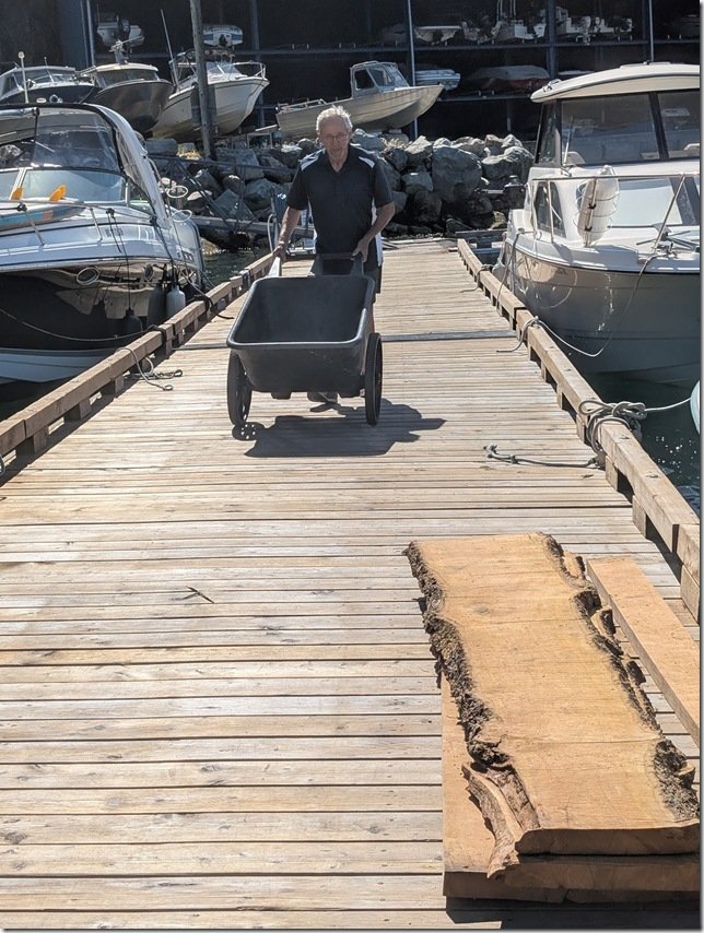 Rick and I carried them down the last way on the ramp and had them all ready to now load onto his boat.
  Easy peasy as we Canadians say and Rick put his boat into gear and we were off on the 10 minute ride over to the dock and then carried them up and loaded into Lance!
 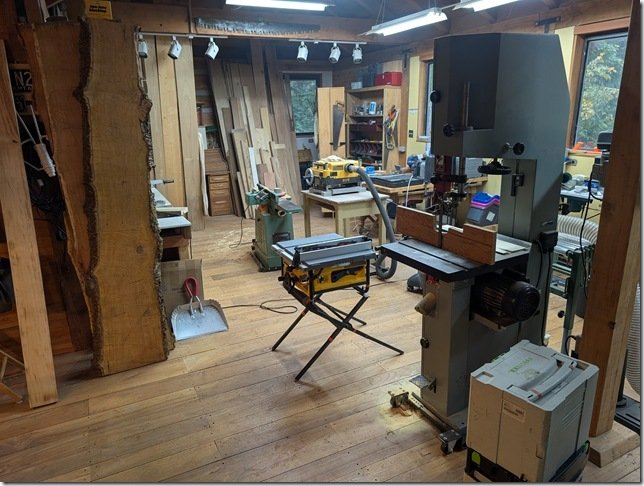 Christine and I bid them all adieu and headed off on the final leg of our cross North America trip to get Lance back to our place on Saturna Island where I carried the planks on their next voyage into my workshop. You can see some of the planks now standing up on edge to the Left of the yellow table saw.
  A few weeks later my awemazing son Skyler came over for a few days to help me out and after a bit more wood wrestling and we had the first slab horizontally on the sawhorses ready for to be cut down to size. What we needed to do is cut some of these into strips about 20mm/ 3/4” square that would be glued to the edges of 13mm/ 1/2” Baltic Birch plywood and then to cut others into very thin sheets that would be glued on top of the edged plywood to create all the drawer fronts and cabinet doors patiently awaiting inside Lance’s Galley.
 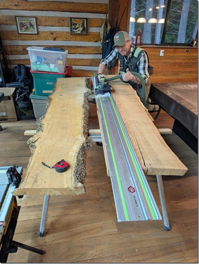 Skyler is a very talented cabinetmaker and woodworker and he had brought over his Fein Track Saw with him which was just the right tool to cut the rough sawn slabs down to more usable size.
 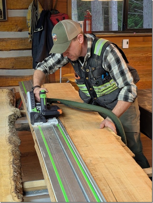 Cherry is a lovely wood to work with and over the years I’ve used it to built quite a lot of furniture and cabinets with.
  These thick planks were a bit of a challenge but Skyler and his saw were up for it
  and along with the table saw we soon had these planks cut into about 150mm/6”wide boards for our next step.
 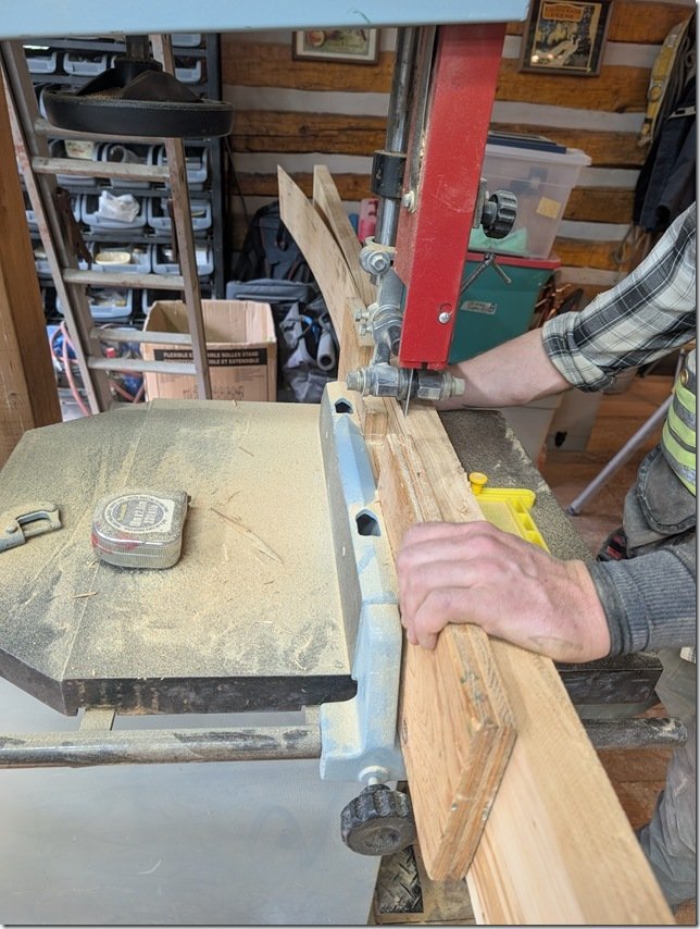 Which was to move them over to the bandsaw which had a sharp new 1” carbide toothed blade I had just bought and fitted. We made up the wooden fence you see here to guide the planks that were now up on their edge ready to be run through that blade a bit like a meat cutter blade shaves thin slices of ham.
 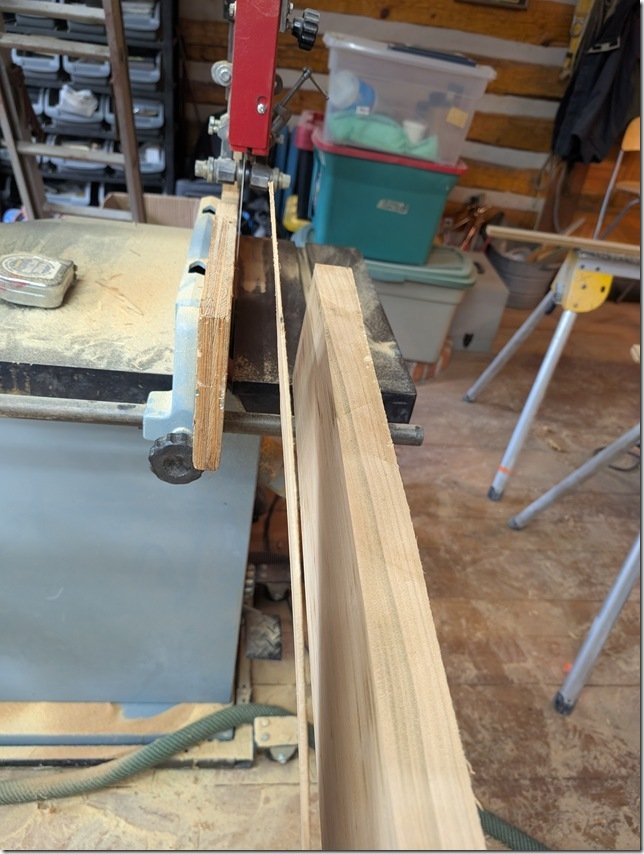 After a few test cuts we had the fence set just right to give us consistently thick slices.
 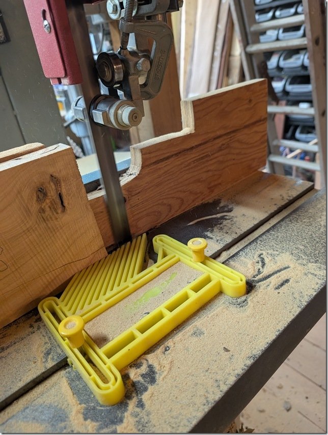 This yellow feather jig clamps to the slots in the bandsaw table and keeps the plank pressed tightly against the side of the fence.
 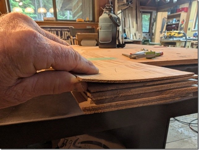 Each slice is about 3-4mm / 1/8” thick and will be the “veneer” that I glue onto all that edge banded plywood drawer fronts and doors.
 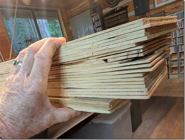 Net result was four of these stacks of the 6” wide Cherry veneer.
  For the solid Cherry edging we needed for the perimeter edges of each Baltic Birch plywood blank we ripped them to rough size using the table saw and then fed them through our thickness planer to take them down to be just a wee bit thicker than the 1/2” plywood so I can trim them down to be perfectly flush with the faces of the plywood.
 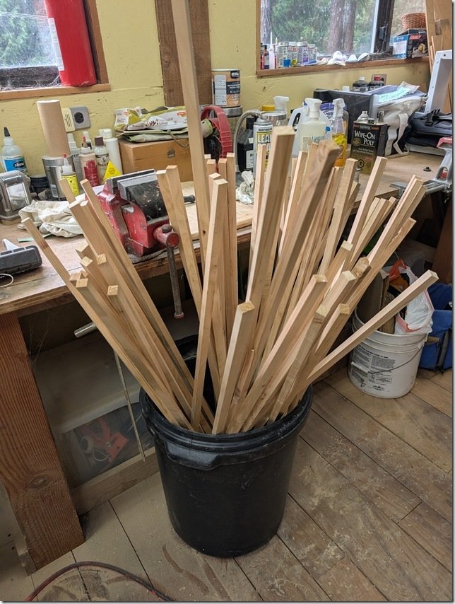 There are a LOT of drawers and doors each of which needs four solid Cherry edges so we set up a bit of a production run between the two of us using the table saw and the thickness planer and started putting them all into this plastic waste can.
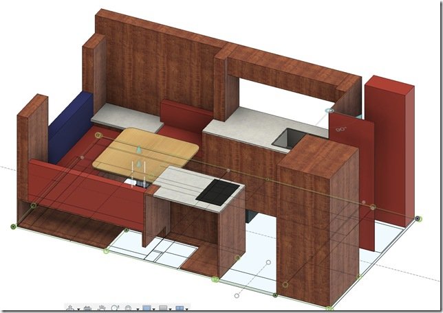 To help with your orientation, this screen shot from my Fusion 360 3D model shows where the Head & Shower are located in the front DS Driver Side of Lance’s Hab/Habitat/Box which is on the far Right of this view.
 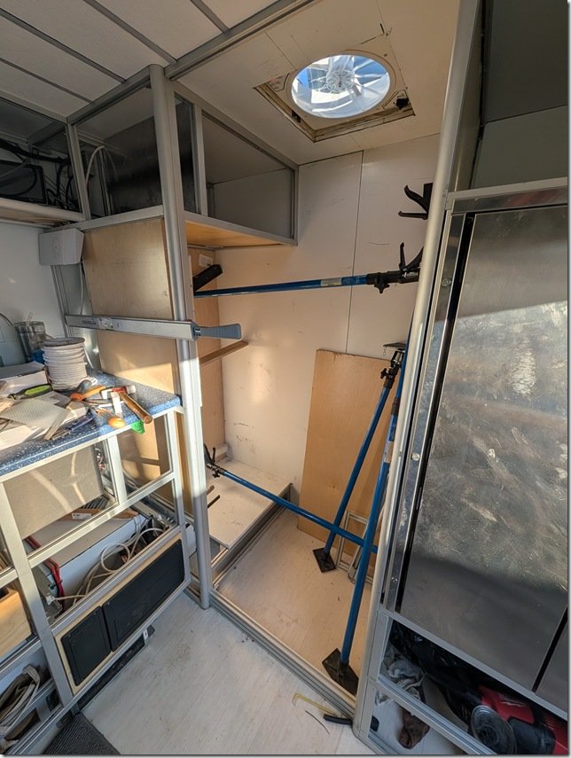 Here is what it looked like IRL (In Real Life) from the inside when I got started. That’s the SS Fridge/Freezer on the far Right, Blue DS Galley countertop peeking through on the Left and that’s the DS Front corner of the Hab in the far middle of this photo. The toilet will sit on top of the raised floor section and I’m getting ready to put in the the shower pan on the lower section of the floor that the blue cargo spreaders are resting on.
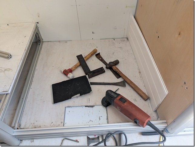 For maximum adhesion of the rigid foam Shower Pan I removed all the LVT vinyl floor planking that covers all the floor area inside Lance’s Happytat.
 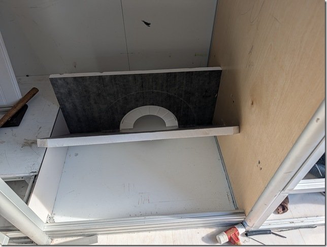 To help with tiling the shower pan and getting the slope to the center shower drain just right, I bought a Vevor shower pan kit that is specifically made for this purpose and adds even more insulation to the shower floor.
 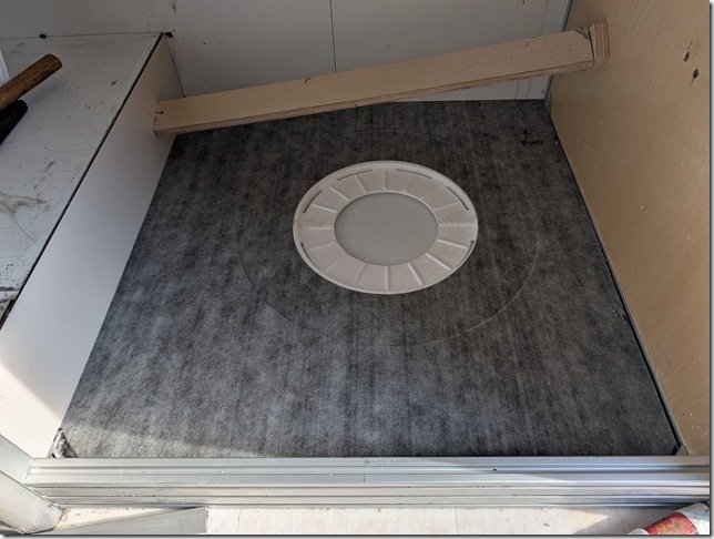 You can see here how the area for the flange of the PVC drain is already pre-cast into the foam and you’ll also note the large circular recess surrounding it for bedding the drain flange into the floor.
 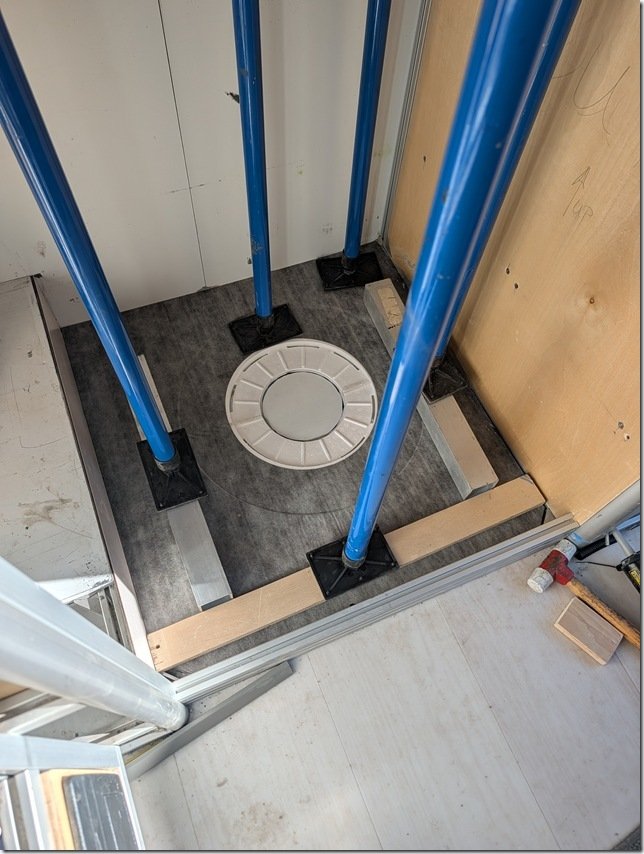 After checking that it all fit just right, I removed the foam pan, applied a silicone based adhesive with my cordless caulking gun (that I’m enjoying more ever time I use!), spread it out evenly with a notched trowel and pressed the floor pan back into place using my trusty cargo spreaders and some aluminium and plywood cauls to press it even and flat.
 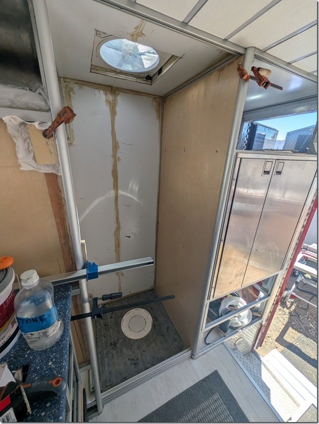 It was difficult to see in the photos above but I also used 1/2” BB plywood to cover the wall between the Shower and the Fridge/Freezer compartment. I caulked all seams and corners with construction adhesive for additional sealing of those.
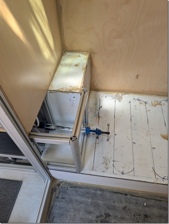 Next I put in this small bit of XAL framing to extend that exterior cabinet “bump” all the way to the inner edge of the Head raised floor. This will also create a handy storage area.
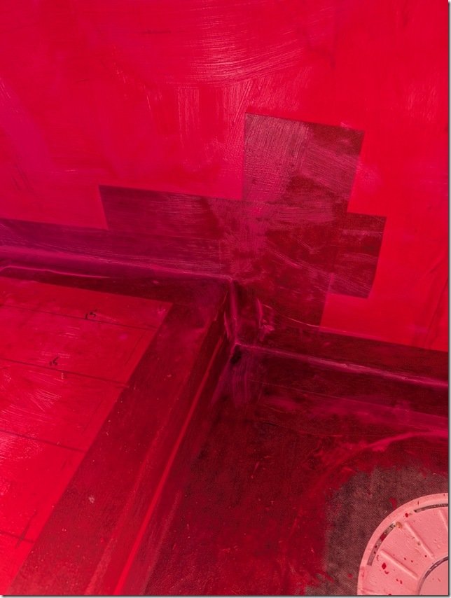 After the first thin coat of RedGuard was on I went around and used more RedGuard to bed in some reinforcing felt that I cut into strips and pressed into all the corners and seams with more RedGuard.
 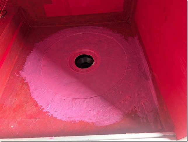 The drain area received several more coats of RedGuard as this will get the most traffic and potential for seepage. The pink colour is from the still wet RedGuard which quickly changes to Red as it dries fully.
 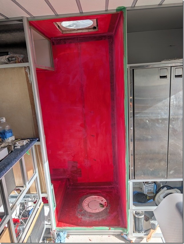 Et Voila!!
 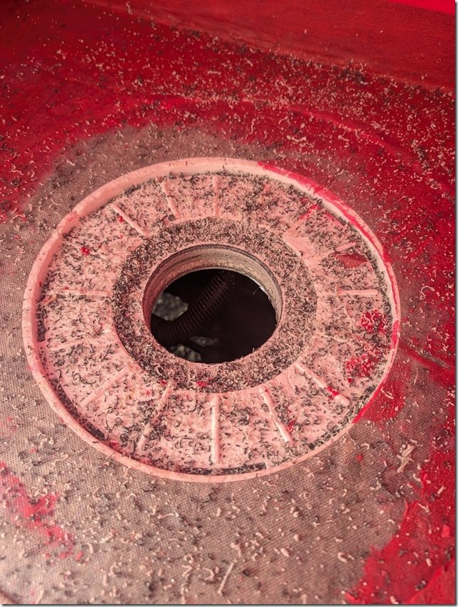 A bit messy but my 11cm/ 4 1/4” hole saw did a nice job of cutting this hole through all the layers of insulation and aluminium in the floor for the PVC drain to set into and exit out the bottom where it will connect to PVC pipe and on to the Gray Water tank. You can also see the 2 inches of insulation that are below the shower floor.
 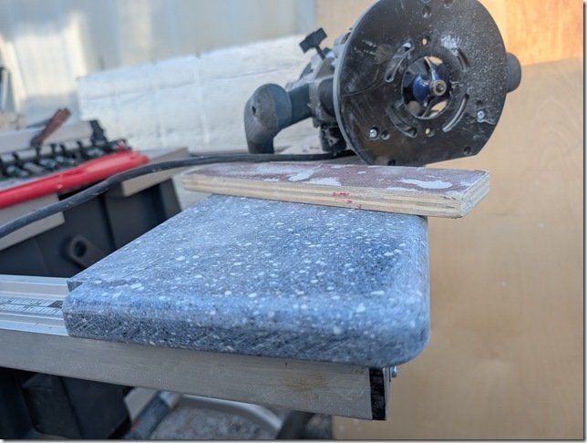 I had some of this Blue Solid Surface acrylic material left over from doing the Galley countertops so I used this to create a nicely contrasting and durable shelf top on that bump out in the Head.
 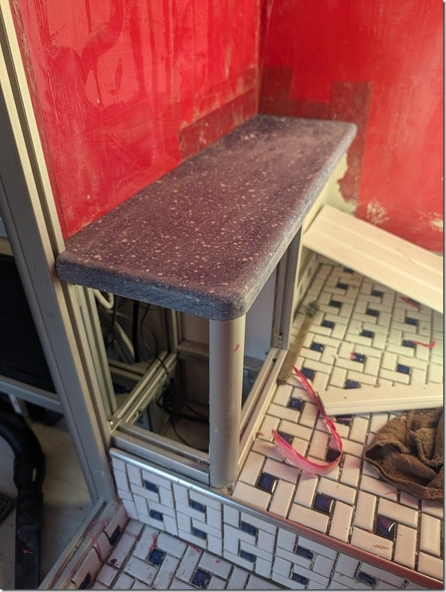 I wanted to get this shelf installed before I started putting in the PVC planking that I’m going to use to cover the walls.
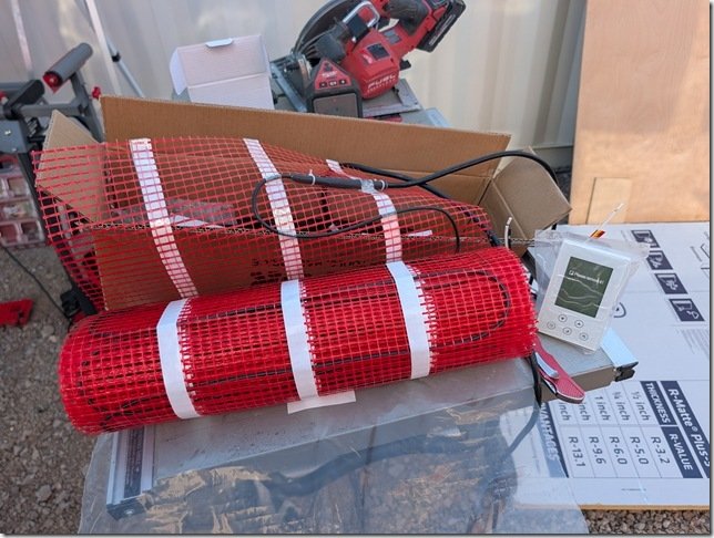 The kit comes with this Orange plastic mesh which the Black heating cable gets attached to.
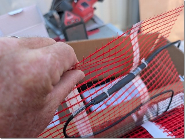 This is the transition piece where the cable changes from the 220VAC power cable to the heated wire. As it is a larger diameter I routed a groove into the ACM flooring so this thicker diameter would sit flush with the floor surface and be better protected.
 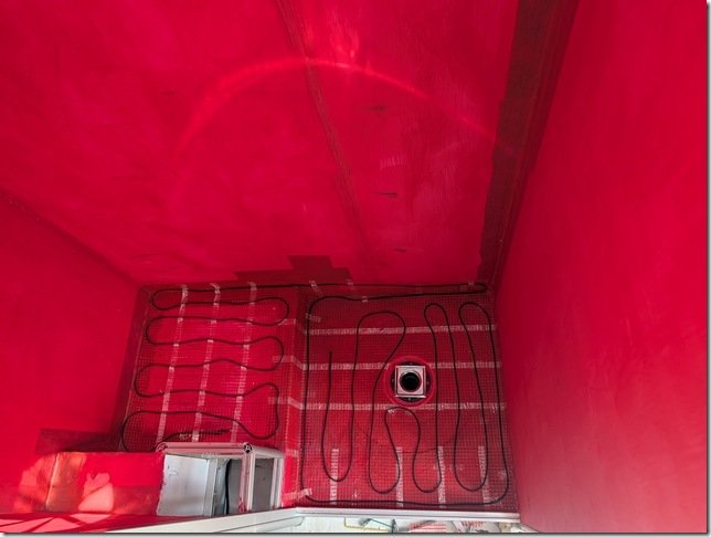 The heated cable is one continuous length and you can not cut this so it took me a bit of planning to get the spacing right but all fit in very nicely and will keep our tootsies warm both when showering and sitting on the Throne!
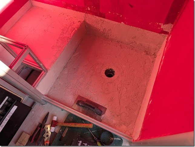 With all the heated cable and mesh in place I mixed up the epoxy thinsulate/mortar and spread out about a 13mm / 1/2” thick layer with a steel trowel and smoothed it all out.
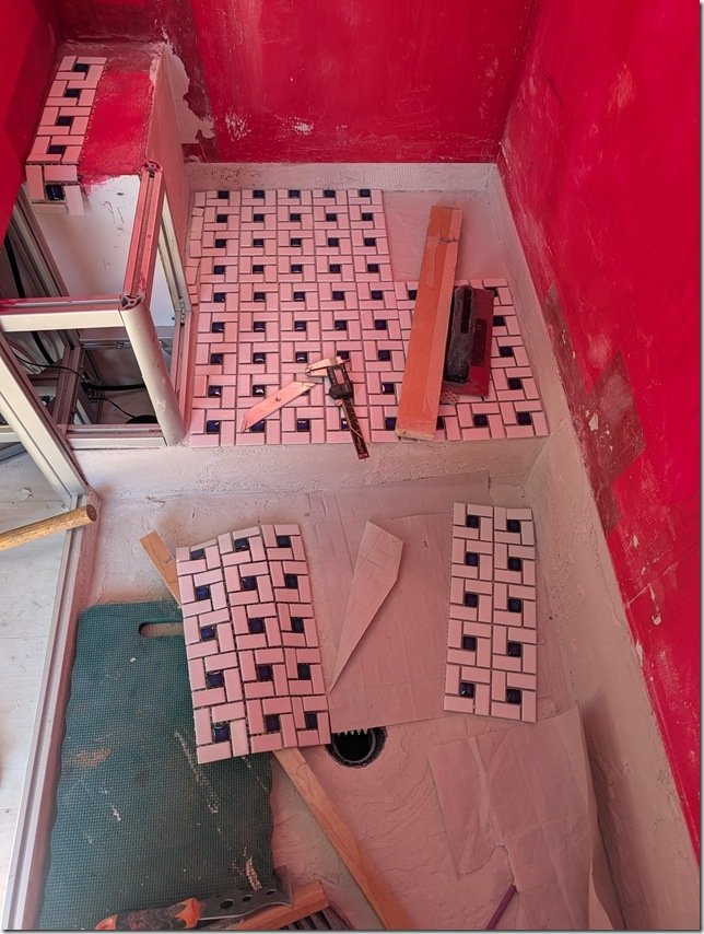 Laying out this type of spiral pattern is a bit tricky and takes some planning to make sure all the corners and joints line up and maintain the pattern. If you look closely you’ll see that you can only get a straight line for butting up against corners or lining up sheets in one place along the larger square formed by each spiral.
 I
I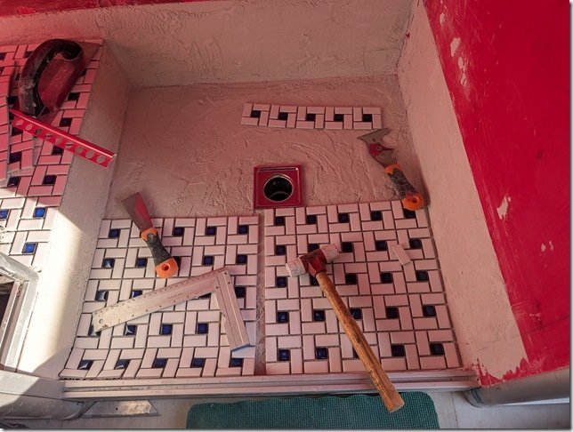 Then I moved onto the Shower floor and started the dry layup there.
 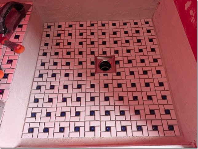 You can see how I needed to trim the tiles a bit along the edges of the square SS drain which I did so that the outer edges of the regular square spiral patterns would match up with the outer edges.
 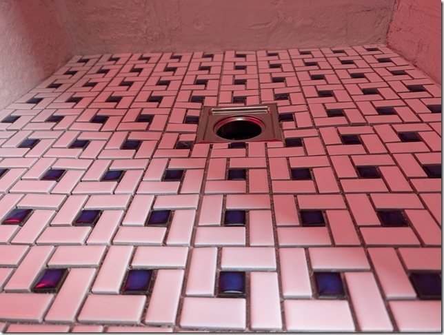 And it all slopes down from the edges to the drain.
 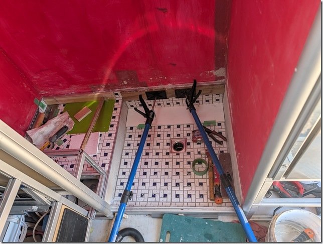 I thought it would look better to create a single upper edge surrounding the whole space so I put in some aluminium edging and tiled up to that along all the sides of the Shower and the Head floors and set them in place.

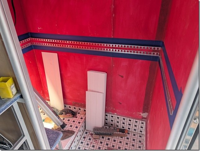 ………. and installed the AL transitions edging all round.
 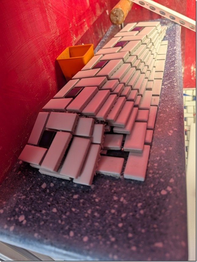 I had enough left over tile to cut these bands off the sheets and used that size to determine the width of the band.
 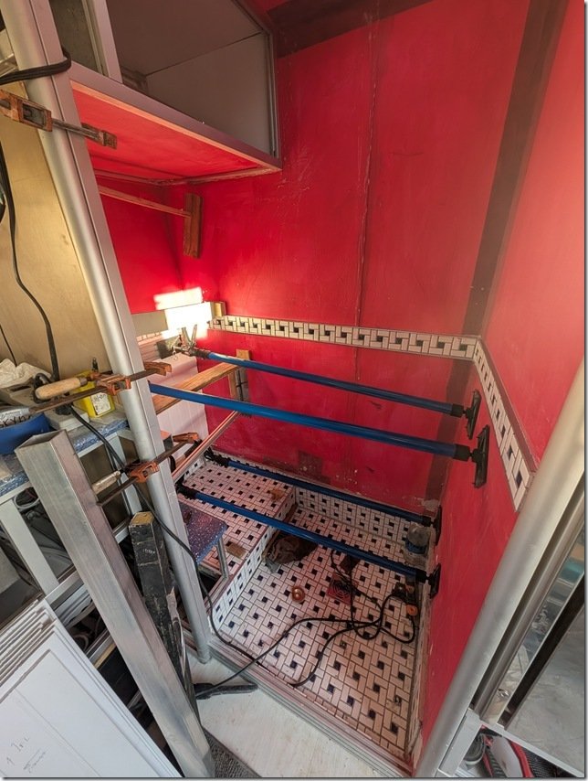 Worked out quite well and now time to put up all the PVC wall planks.
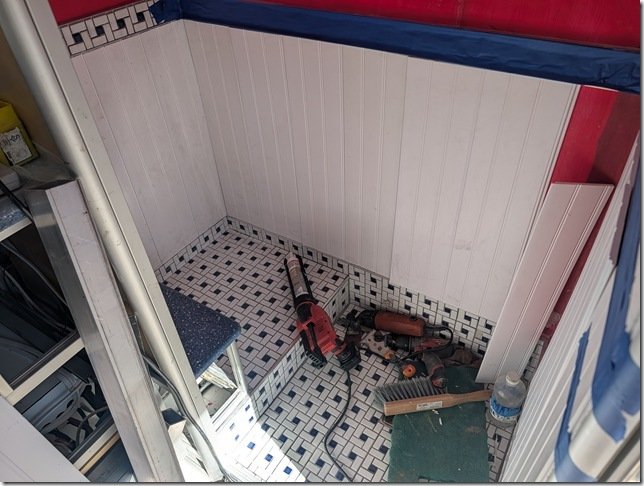 It was quite quick and easy to cut the 8ft long PVC planks to a nice fit between the top and bottom edges of the aluminium edging there the tiles start and stop.
 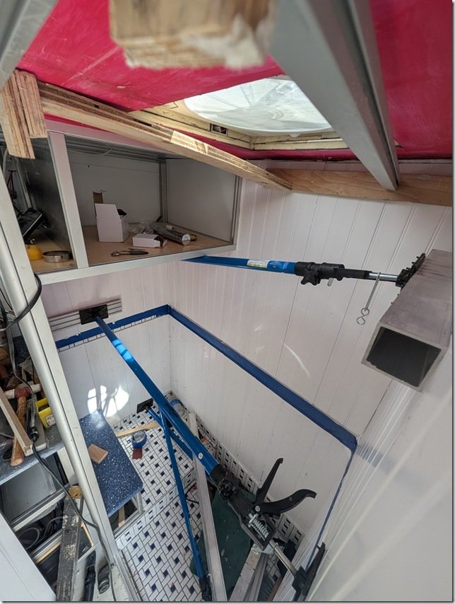 The cargo spreaders and some square aluminium tube cauls helped to hold the PVC planks flat while the silicone adhesive cured overnight.
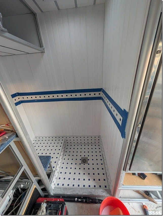 With the wall planks all done I could now grout all the tiles in this band and on the floors to finish the tiling.
 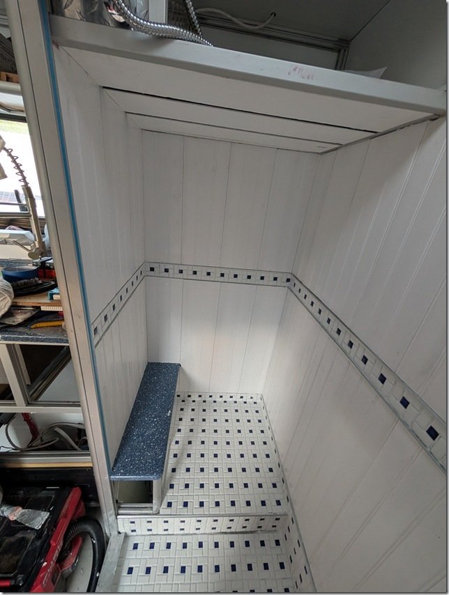 I did the ceiling with the same vinyl planking with a different pattern on it that I used for the ceilings in the rest of Lance. As with those other ceilings, I put in a strip of dimmable LED’s between each plank but more on that a bit later.
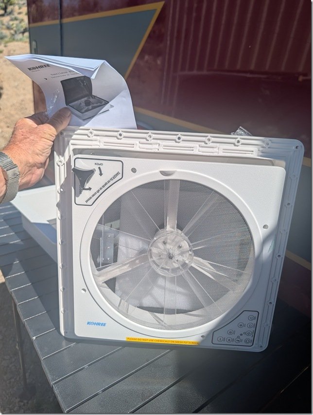 I’m not a big fan of the popular variations of the MaxFans that much of the RV and Van world seem to use and wanted to keep our overall vehicle height to a minimum and we’re at 2.9m / 9’ 5” right now with the solar panels and roof vent. So this Kohree vent unit seemed to check all our boxes.
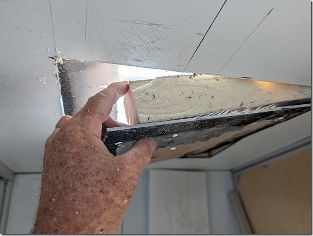 There are three thick aluminium plates in the roof of Lance, one for the top skin, the layer you can see here that forms the internal ceiling of the ambo box and then ……
 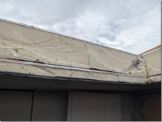 ……… the final layer of 5mm thick ACM that I installed for the ceiling surface below the additional layer of 20mm IPS foam insulation.
 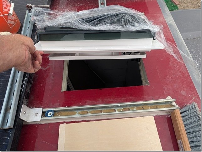 The vent dropped in just right.
 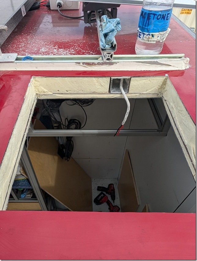 I used this 2×2” square AL ceiling beam for a conduit for the wires to power and control the fan.
 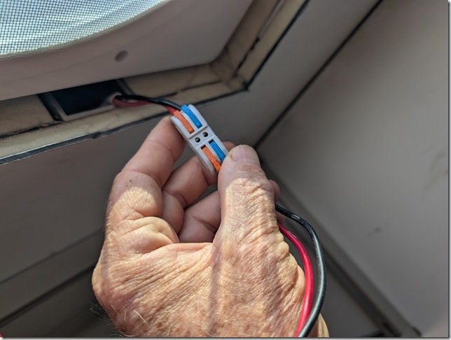 I’m a BIG fan of these WAGO wire connectors and have used them throughout the build. They worked well to connect these 12VDC power wires to the fan and then tuck nicely into that square AL tube.
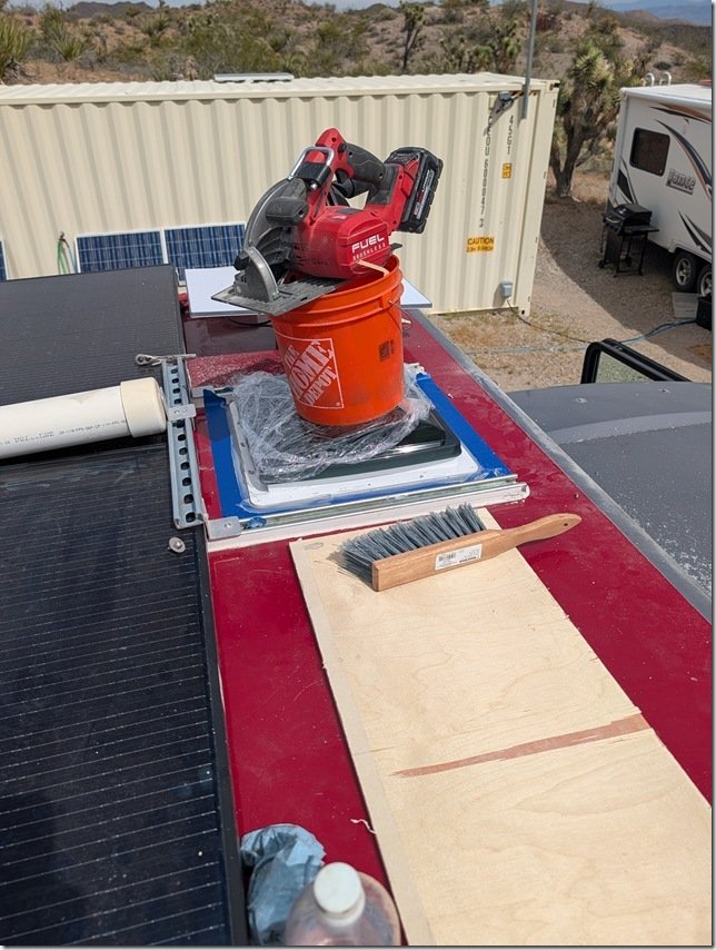 ………. bedded the vent into the roof with 3M 5200 sealant and some makeshift weights to let it cure overnight.
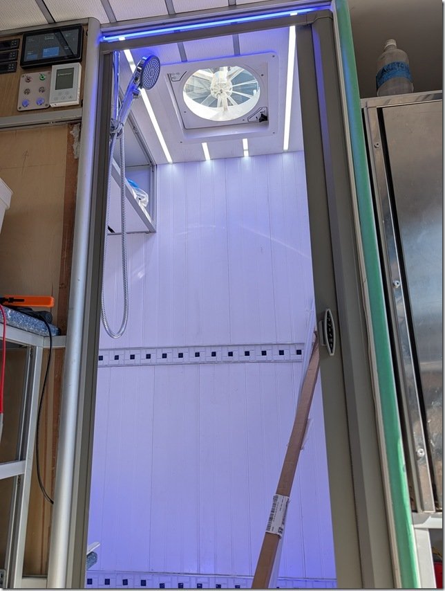 Worked out well to provide Goldilocks just right lighting both night and day.
 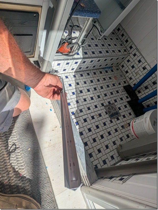 One last detail for those few times (so far) either of us needs to get up and use the Head in the middle of the night, I wanted also have some indirect low level lighting inside the Head & Shower area. So I installed some of these 45 degree angled aluminium extrusions in hidden areas such as under the door sill into the Shower you can make out below my hand and another under that little Blue shelf in the Head.
 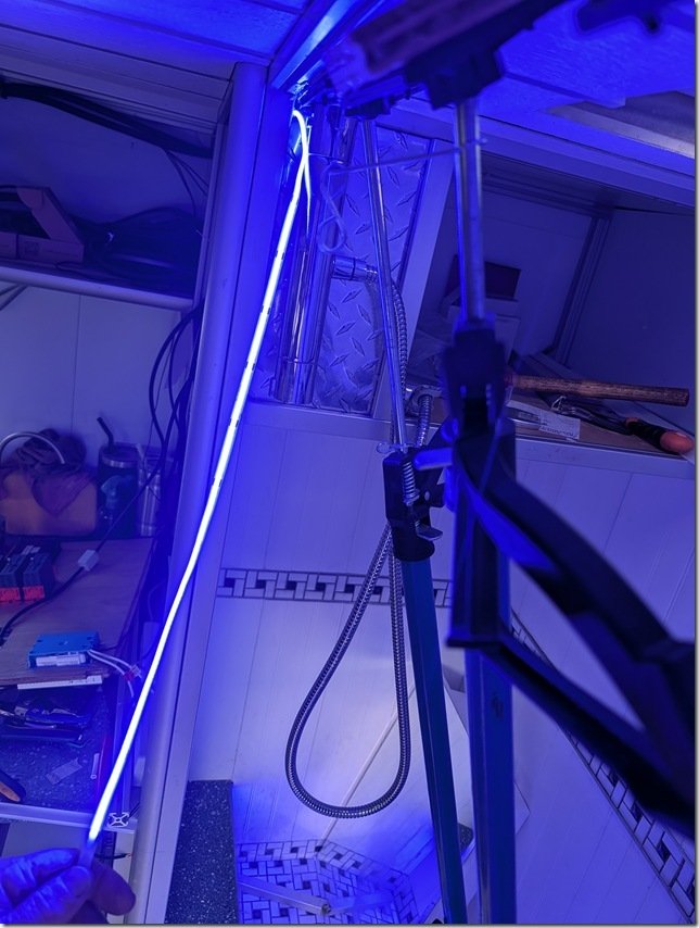 To help keep our night vision and add a bit of “ambiance” I used these Blue LED strips which are also dimmable to whatever level of Blue light you’d like.
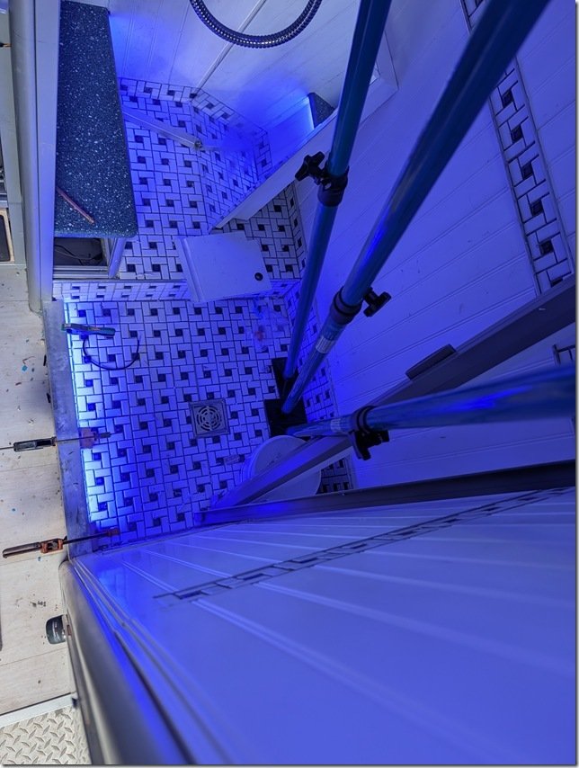 Testing out the LED strip tucked in below the door sill into the Shower.
 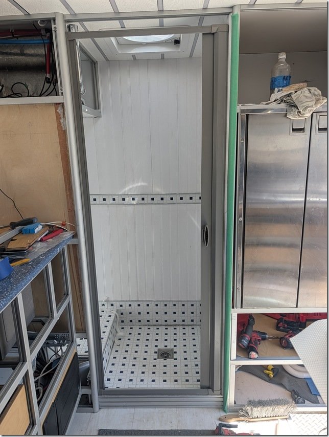 After some debate and research we decided to go with this retractable shower door that rolls up when OPEN like this
 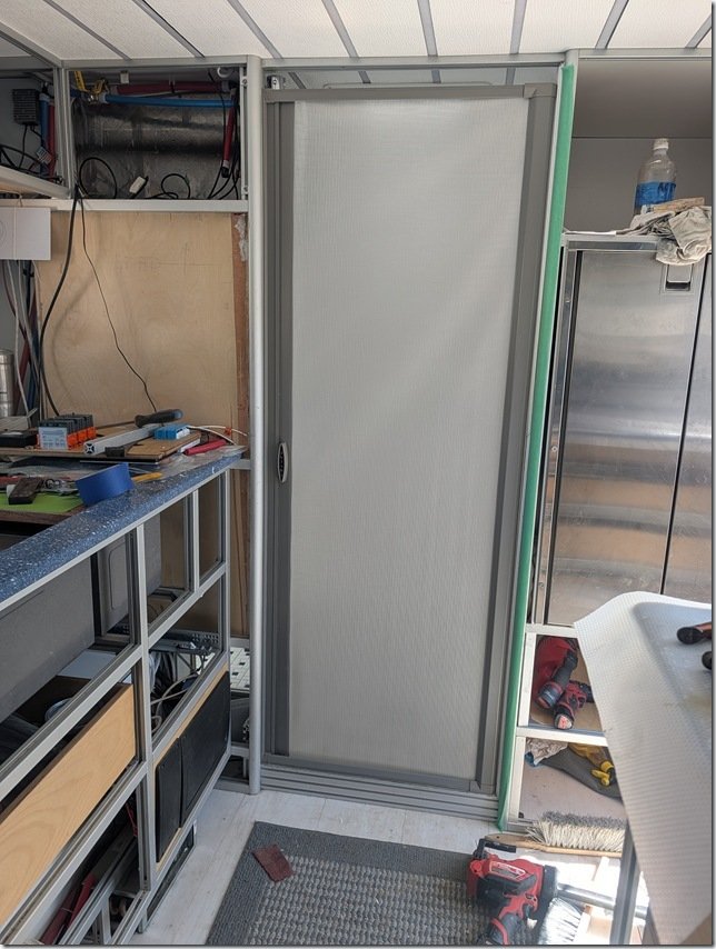 ….. and then rolls out to seal and CLOSE like this.
 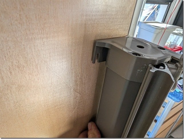 The flexible material rolls up on a spring loaded shaft hidden neatly inside this cassette that mounts to the left side of the door.
 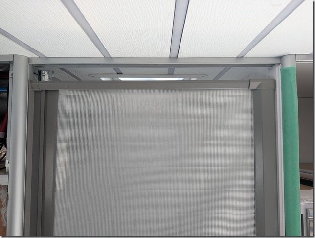 The “door” slides on tracks concealed inside the AL extrusions top and bottom and I left a small gap at the top to help with air circulation.
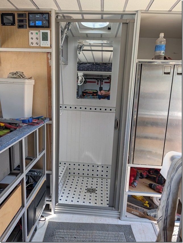 And then mounted this mirrored Medicine Cabinet on the rear wall to finish things off.
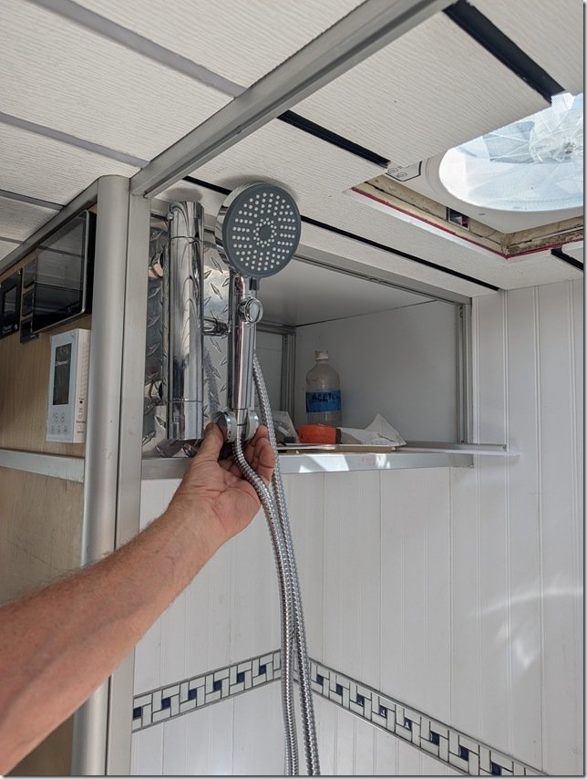 …… connected it to a thermostatic controlled mixing valve faucet. These are great for maintaining a whatever water temperature you set it to coming out of the shower head. The button allows you to turn the water on and off as you wish to conserve water and have it off when you want to wash your hair, shave, etc.
 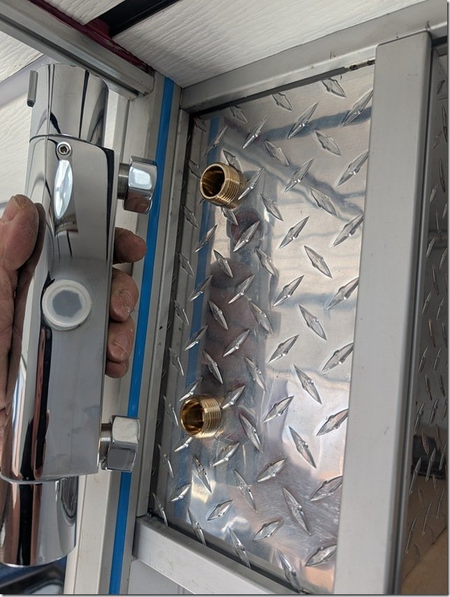 The SS cylindrical knob on the top end rotates to set the temperature and the one on the bottom controls the water flow volume.
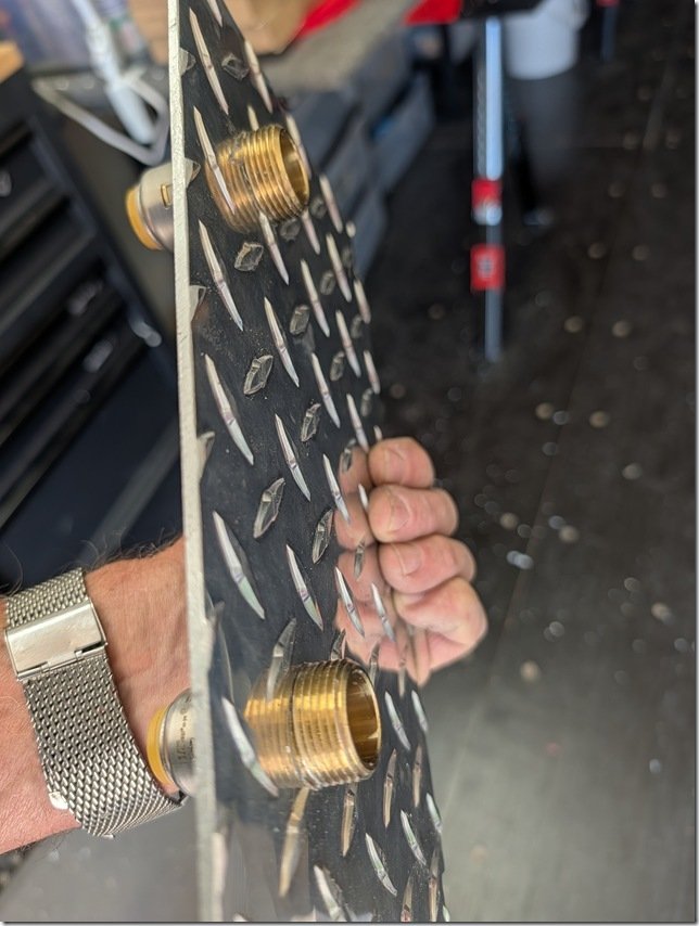 I drilled and threaded this plate to mount these two brass fittings for the thermostatic valve to attach to on the outside and push-connect fittings on the other side …………

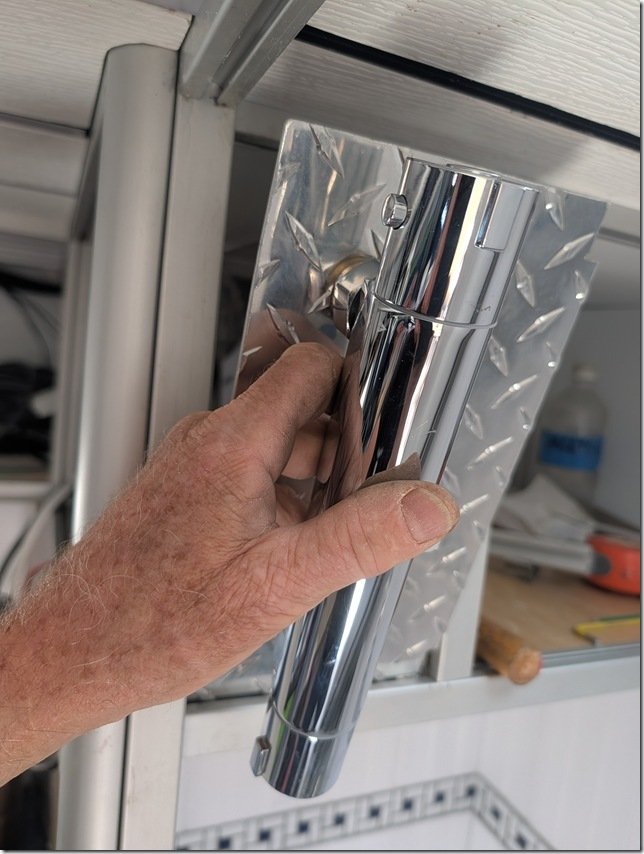 The whole assembly then fits securely into the slots in the XAL framing.
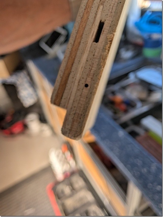 I cut this rabbet or tongue on the bottom edge that is a snug fit into the groove on the bottom length of XAL framing.
 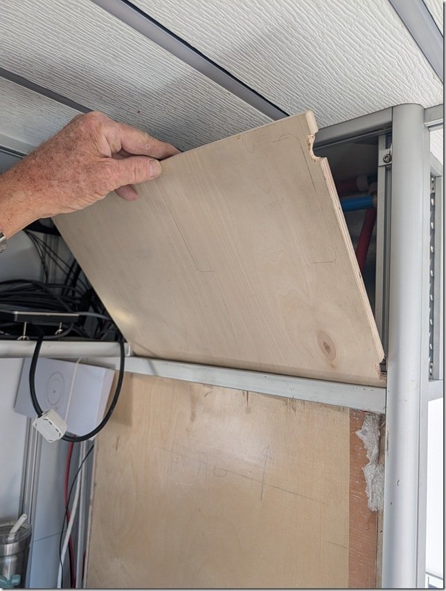 The way it works is that you first put the bottom tongue into the groove and then ……..
 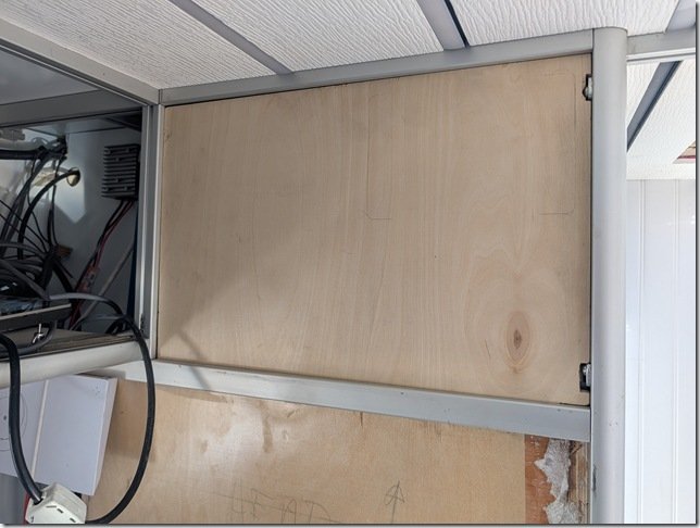 …………… tip the panel up into place.
 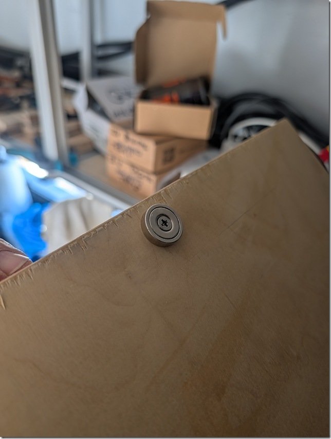 To hold this and likely all the panels in Lance securely in place, I’m trying out using these very strong round “donut” Neodymium magnets. This one is a 40 pounder, meaning it takes about 40 pounds of pull to remove. These magnets are available from less than one pound up to over one hundred.
 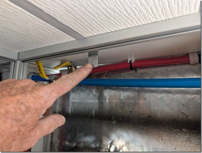 All the metal in Lance is aluminium which of course isn’t magnetic so cut a short 5cm/2” length of steel flat bar and drilled a 6mm hole in one end so I can bolt it to a T nut captured in the XAL slot on the back here. Worked out even better than I hoped and the panel snaps into place with a good “thud” and locks the whole panel tightly in place.
 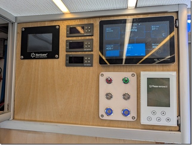 Here is what the panel looks like so far. White thermostat for the heated floors in the Head & Shower in the bottom right (currently turned off) and the Victron Cerbo GX touch display above it and switches for things like water pump, Starlink power and the thermostatic controllers for the heated main cabin floors over to the Left.


 To max out volume of storage areas I framed in the space above the Joolca “Gotta Go” separating toilet to create an overhead cabinet.
 As you may have noticed I am working my way counterclockwise around the interior spaces and the last part of the main framing for the primary cabinetry is the currently empty area on the far Left you see here, which will be the Drivers Side Galley.
 The model gives me the precise length of each piece I need to cut on the cut off saw and how each joint goes together. Each of those four vertical spaces will be filled with drawers of different heights and the vertical XAL front and rear provide very strong attachment points for all the undermount drawer slide hardware that I’m about to order.
  Speaking of windows, we have our always alert security guards keeping a close eye on the comings and goings of the various others we share this fabulous area. No need for any worry about our safety with these two vicious watch dogs on the job!
  While we don’t see too many people, which is just the way we like it, there is lots of life to see out our windows including the real life versions of Wile E. Coyote & Roadrunner, rabbits large and small, lots of mice and squirrels on the ground and ravens overhead.

 Here is a skeleton view of the XAL bed frame in Blue which will then have a plywood panel spanning across the support bars with the mattress tucked firmly inside the outer XAL bed frame.

 All four actuators plug into this FLTCON-4 central control box which provides the 24 volts for each motor.
 Last piece of this automated lifting bed system is this small set of buttons that is also plugged into the control box. Once the interior panels are all installed this will be the only part you will see and will likely be mounted somewhere out of the way but easily reached when we want to move the bed Down to Sleep or Up to eat.
  The Up/Down buttons allow you to move the bed Up/Down to any position you want and then you can save this position into memory of button 1, 2, 3 or 4.
 I work hard to maintain my well deserved reputation as a pack rat and so I had kept ALL the wires, materials, nuts, bolts and hardware when I fully gutted the original Horton ambulance box and took it down to the bare AL frame. One of the pieces of aluminium I kept was this C-channel and it turned out to be my just right Goldilocks solution for building the saddle blocks I would bolt to the cars on the actuators.
  I cut the C-channel into four short pieces that were the same length as the Black Cars on the actuators.
  The width of these Black Nylon Cars was just a wee bit larger than the inside width of the AL C-channel so I carefully guided each actuator through my table saw and trimmed off about 2mm from each side.
  Which allowed them to be a slight press fit onto the Car.
  The inside corners of the C-channel have a radius to them but it was easy to file the corners of the Nylon Cars to match and Voila! A perfect fit.
  Progressive Automation manufactures the thick Black Nylon Cars with three threaded mounting holes on each side which go all the way through the body of these Black Cars; a large M10 in the middle with two M6 on either side, so I drilled out matching holes in the sides of the AL C-channel saddles so I could very securely attach each saddle its Black Car mate.


 …….. to make these matching L-bar mounting brackets ………..
  ………. which I then bolted to the C-Channel saddles with the Heim Joint sandwiched between the two “ears” of the brackets and through bolted.
  Worked very well and I could then bolt each Heim Joint Saddle to its matching Nylon Car. I then bolted each linear actuator to the vertical XAL support posts using some AL bar stock that I cut to be thick enough to keep the inner surface of the AL saddles spaced clear of the inside of the XAL posts and they moved up and down.
 The sides of the bed frame are made from lengths I cut from 3” x 1” XAL and carefully clamped each one in place so I could precisely mark the center of each SS insert and then I drilled undersize holes through the XAL. As you can see in the photos above these SS inserts are tapered so I used my handy dandy Dremel tool with a rotary carbide cutter to enlarge these holes and carefully hand fit the SS inserts to be a slight press fit into the XAL.
  I
I I allowed about 5mm / .2” clearance between the moving bed frame sides and the XAL posts so it is a very close fit that was relatively straight forward to adjust by turning the threaded SS inserts with a wrench on the flats I ground on each one (see photos above).
  The power/comm cables on each actuator need to be extended but I was able to just plug each cable into the control box and hang it in the center which allowed me to test out the whole assembly.


 We continue to work away at getting things setup here on “Road Runner Ranch” and this arial shot from Christine’s drone video that you might have seen in the previous post, shows how we are setup so far.
  The 40’ shipping container above on the left is what I’m setting up for my workshop with Lance parked right beside.

 Looking forward from about mid way inside Lance’s “Happitat” the blank wall on the left is the front wall with the cab on the other side and the main entry door that is on the passenger side PS in the right corner. I’ve put in a scrap of 3/4”/20mm plywood to create a desk for myself on what will eventually become one of the two galley countertops with a larger one yet to be framed on the opposite left or driver side DS.
  Here is a sample of a length of the XAL with several different corner brackets that bolt into the T track grooves in the XAL which turn this into a giant adult version of the Erector sets I used to love playing with as a young boy, long before many of you were born!
  I’m working my way somewhat counter clockwise around the Happitat walls so my next focus was the XAL framing you see now in the front right PS corner. The Blue poles you see ratcheting cargo support bars that have proved indispensable to me for holding things in place as I build.
  This full height cabinet will have our fridge/freezer mounted inside the large opening you see here with lots of storage in the spaces above and below.
  This front DS front corner is a bit more complex as the large vertical exterior access cabinet is also in this corner and it is where I’ll be installing Lance’s whole electrical system with three large lithium batteries on the very bottom and then all the other components such as 12VDC to 120/240VAC inverters, battery chargers, and much more mounted this exterior locker.
  This will give you a sense of the size and shape of the server rack style lithium LiFePO4 batteries that will provide all the 12VDC and 120/240VAC electrical power in Lance.
  For those interested in the details, this shot the label on one of the three batteries will give you all the numbers.
 I knew that the batteries were going to be a very close fit and I had built the framing for them back when we were in Klamath falls but now was the moment of truth to see if they actually fit?!!


 With the shower area in the center area the whole bathroom space becomes feels very large and open both when using it as a shower and when seated on the throne. I had my Beautiful Bride check it all out in person this morning and got the two thumbs up so the framing progress can now continue.
  I
I We continue to get sunsets like this almost every evening and sunrises are pretty spectacular as well so we continue to enjoy our new location a bit more each day.


Recent Comments