

Heads Up! Lance XRV progress update; 7 June, 2026
I appreciate your patience as I continue to try to catch up with posting updates here on my progress with the transformation of Lance from his start as a 2016 Kenworth T270 Medium Duty ambulance from a fire department in Wisconsin to an eXtreme RV or XRV for us to continue our explorations via our Land Yacht. I’ve got a few more updates to do but I just about have you up to date on all the various projects within Lance and this one will take you through the completion of the Head & Shower area inside Lance’s Hab/Habitat/Happytat ambo box.
Last month, May 2026, while I was still at our place down in the very southern tip of Nevada which we call “Road Runner Ranch”, I was able to finish building out the Head and Shower area in Lance.
* FYI, Christine and I are still sailors at heart so the Bathroom will always be the Head and the Kitchen will always be the Galley for us.
I drove Lance up to our place on Saturna Island mid May and am now working up here at finishing off the interior while we are up here through end of August.
Here is what I was able to get done before that drive;
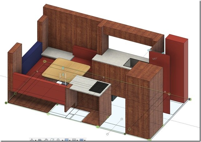 To help with your orientation, this screen shot from my Fusion 360 3D model shows where the Head & Shower are located in the front DS Driver Side of Lance’s Hab/Habitat/Box which is on the far Right of this view.
The Settee & table are at the opposite back end on the far Left with the Galley counters spanning both sides in the middle.
- Note: You can click on any photo to enlarge it.
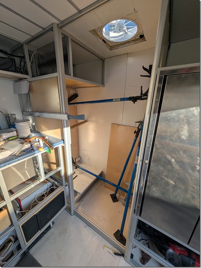 Here is what it looked like IRL (In Real Life) from the inside when I got started. That’s the SS Fridge/Freezer on the far Right, Blue DS Galley countertop peeking through on the Left and that’s the DS Front corner of the Hab in the far middle of this photo. The toilet will sit on top of the raised floor section and I’m getting ready to put in the the shower pan on the lower section of the floor that the blue cargo spreaders are resting on.
The framed in area above the Head will be a storage cupboard on the larger Right side portion and then the smaller space created on the Left will be a service area for plumbing and electrical which I’ll cover later on in this post.  I started prepping the interior by gluing 1/2” Baltic Birch plywood on the XAL eXtruded Aluminium framing of the two walls you see here on the Left and Rear. I use these adjustable Blue Cargo Spreaders (from Harbor Freight) all the time and here they are helping apply pressure to the freshly glued in BB plywood panels to keep them flat and straight.
The small box protruding into the Head area on the bottom Left is the front end of the large middle exterior compartment you saw me filling up with all the plumbing and heating systems in the previous post. 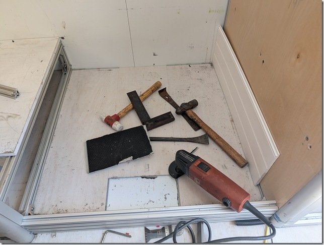 For maximum adhesion of the rigid foam Shower Pan I removed all the LVT vinyl floor planking that covers all the floor area inside Lance’s Happytat.
 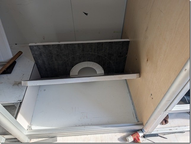 To help with tiling the shower pan and getting the slope to the center shower drain just right, I bought a Vevor shower pan kit that is specifically made for this purpose and adds even more insulation to the shower floor.
It is covered with a thin gray felt that grabs the thinsulate/mortar bedding compound I’ll be using to bed in the electric grid for the heated floor and the ceramic tiles.
Very nicely designed bit of kit and the floor foam is cut in half with the felt glued on top to act like a hinge and made it much easier to press fit the floor into place after cutting it to size. 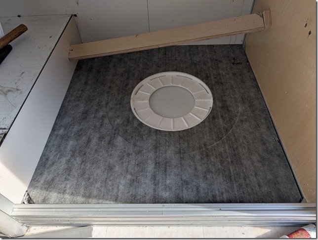 You can see here how the area for the flange of the PVC drain is already pre-cast into the foam and you’ll also note the large circular recess surrounding it for bedding the drain flange into the floor.
 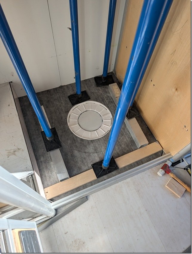 After checking that it all fit just right, I removed the foam pan, applied a silicone based adhesive with my cordless caulking gun (that I’m enjoying more ever time I use!), spread it out evenly with a notched trowel and pressed the floor pan back into place using my trusty cargo spreaders and some aluminium and plywood cauls to press it even and flat.
 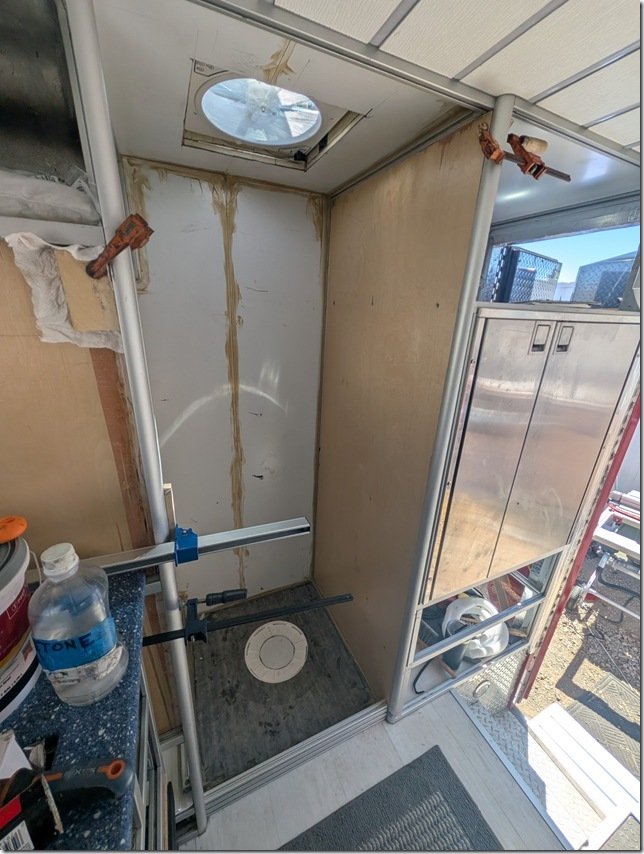 It was difficult to see in the photos above but I also used 1/2” BB plywood to cover the wall between the Shower and the Fridge/Freezer compartment. I caulked all seams and corners with construction adhesive for additional sealing of those.
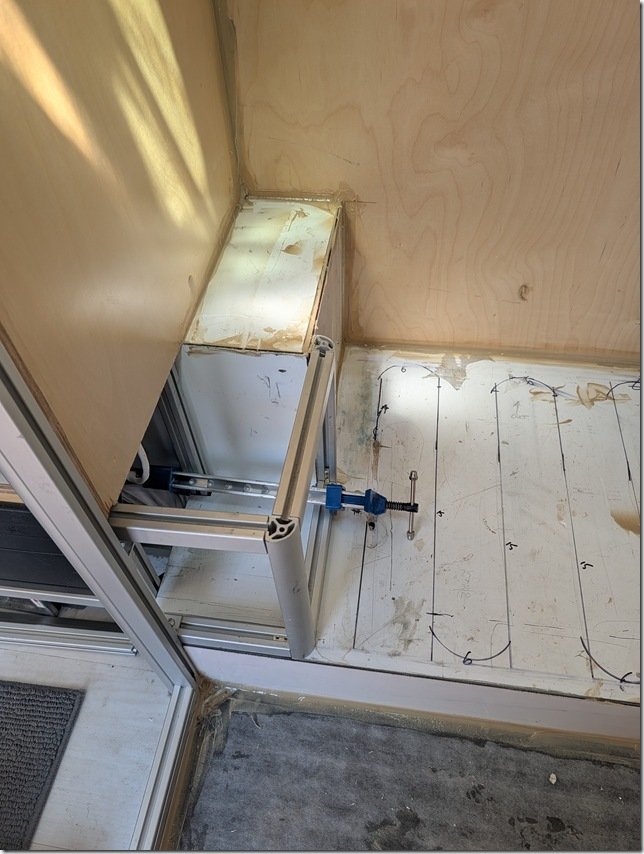 Next I put in this small bit of XAL framing to extend that exterior cabinet “bump” all the way to the inner edge of the Head raised floor. This will also create a handy storage area.
The black lines you see on the White ACM Aluminium Composite Material of the Head Floor is from me laying out the spacing for the heated floor electric grid you’ll see a bit later below.  Now it was time to completely waterproof every surface inside the Head & Shower to ensure that there are no leaks in the future. I used the ever popular RedGuard and brushed it on all the surfaces.
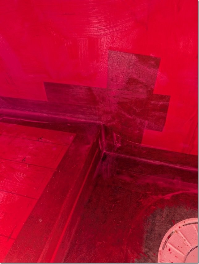 After the first thin coat of RedGuard was on I went around and used more RedGuard to bed in some reinforcing felt that I cut into strips and pressed into all the corners and seams with more RedGuard.
 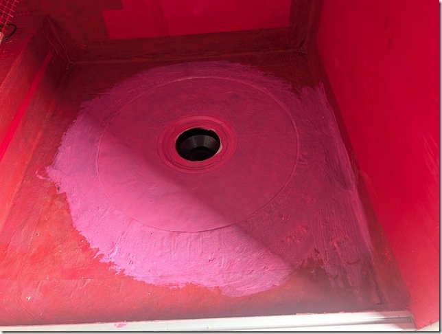 The drain area received several more coats of RedGuard as this will get the most traffic and potential for seepage. The pink colour is from the still wet RedGuard which quickly changes to Red as it dries fully.
 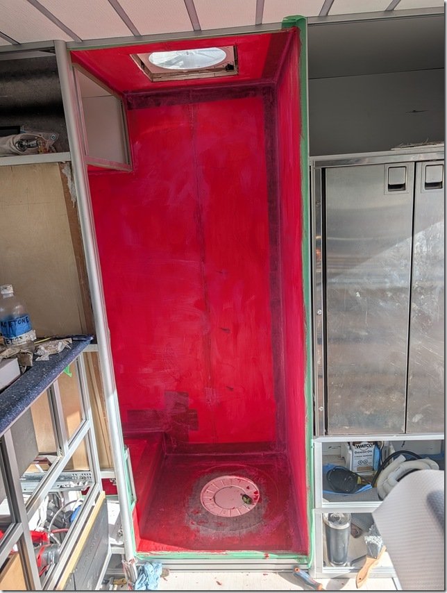 Et Voila!!
A very Red and very waterproof Head & Shower area. 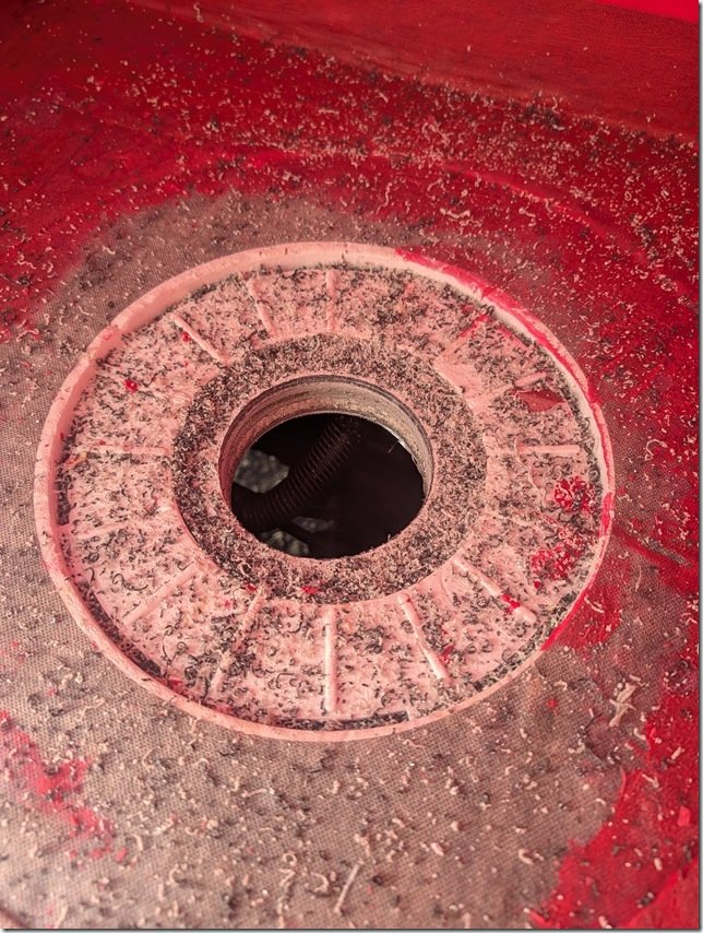 A bit messy but my 11cm/ 4 1/4” hole saw did a nice job of cutting this hole through all the layers of insulation and aluminium in the floor for the PVC drain to set into and exit out the bottom where it will connect to PVC pipe and on to the Gray Water tank. You can also see the 2 inches of insulation that are below the shower floor.
 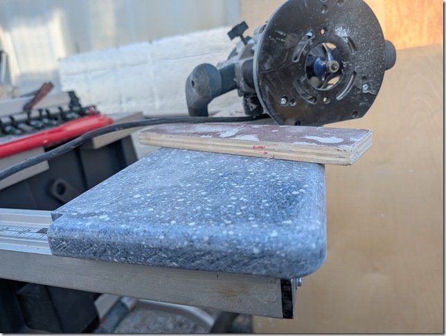 I had some of this Blue Solid Surface acrylic material left over from doing the Galley countertops so I used this to create a nicely contrasting and durable shelf top on that bump out in the Head.
This solid acrylic material is heavy but is very nice to work with; cuts easily and cleanly with regular carbide saw blades and router bits and then sands/files nicely to create a polished surface. 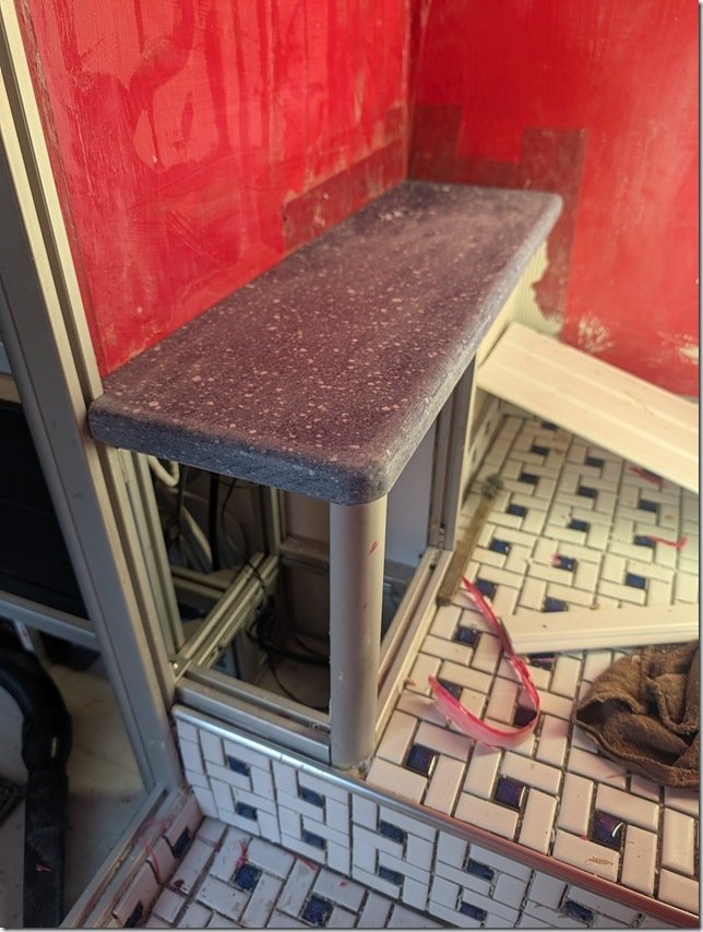 I wanted to get this shelf installed before I started putting in the PVC planking that I’m going to use to cover the walls.
TOASTIE TOOTSIES!
As I mentioned in the previous post about our diesel powered Oasis Zephyr boiler, the rest of the floors inside of Lance are heated via the hot glycol (anti-freeze) pumped out of that boiler and flowing through the loops of 1/2” PEX-A tubing embedded into the insulated foam below the LVT vinyl plank flooring. But I wanted to be able to control the heated floors in the Shower & Head separately as it is always nice to have warm shower floors even in warm weather.

So I opted for another Vevor product, this heated mesh flooring kit that runs on 220VAC and has its own thermostat. 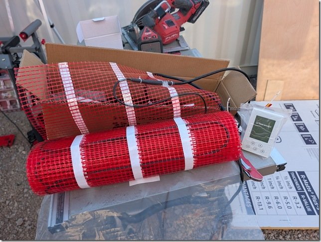 The kit comes with this Orange plastic mesh which the Black heating cable gets attached to.
Also came with this every nice digital thermostat for controlling and reporting on the heated floors. 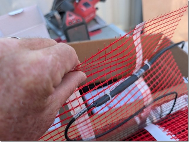 This is the transition piece where the cable changes from the 220VAC power cable to the heated wire. As it is a larger diameter I routed a groove into the ACM flooring so this thicker diameter would sit flush with the floor surface and be better protected.
 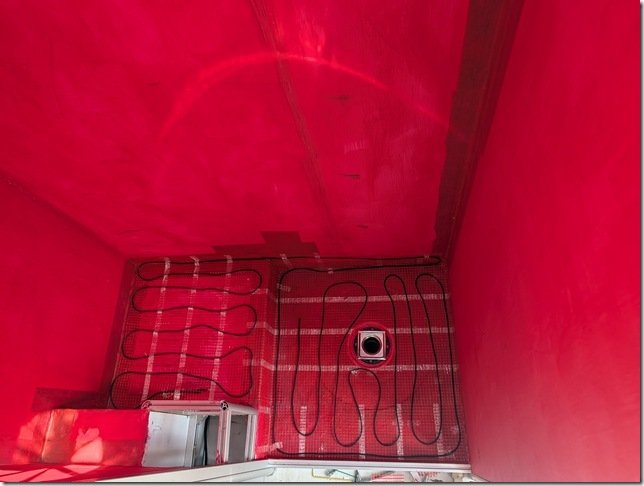 The heated cable is one continuous length and you can not cut this so it took me a bit of planning to get the spacing right but all fit in very nicely and will keep our tootsies warm both when showering and sitting on the Throne!
There is also a temperature sensor that gets embedded in the floor and provides this data to the thermostat so it can maintain whatever floor temp you set. I put this inside a length of protective tubing and that’s the L shaped length you see here which then exits out the side wall and goes up to the thermostat. I put this sensor in this larger diameter tubing so I could remove and replace the temp sensor if it should ever fail. 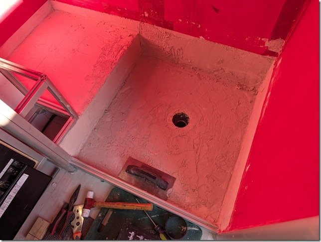 With all the heated cable and mesh in place I mixed up the epoxy thinsulate/mortar and spread out about a 13mm / 1/2” thick layer with a steel trowel and smoothed it all out.
Didn’t get a photo when it was done so this is part way through the process. Finally ready to start tiling!
TILE TIME:

We found this Blue & White Spiral pattern ceramic tile online and both really liked it so that’s what is going on the floors. Comes in these larger approximately one square foot sheets with individual tiles glued to a mesh on the back which makes handling and setting them much easier. 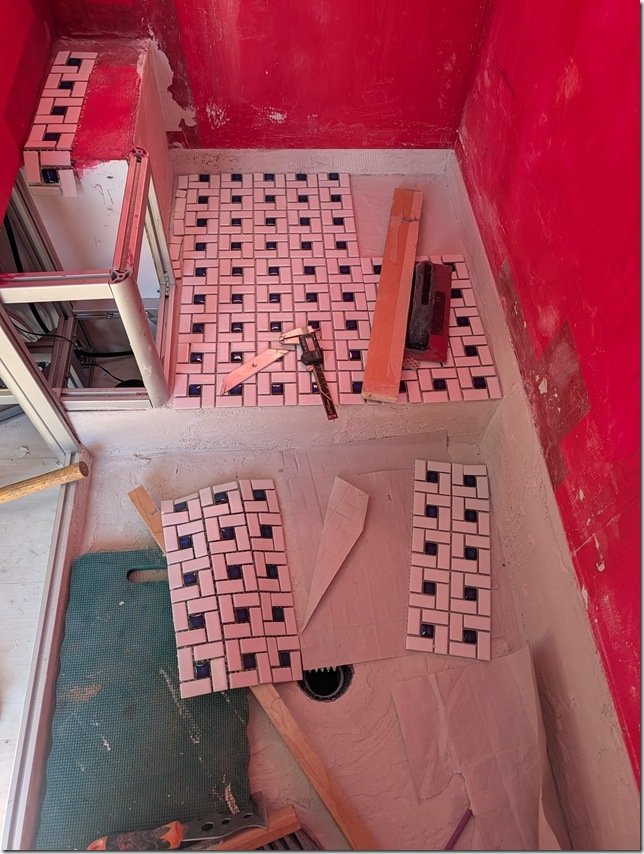 Laying out this type of spiral pattern is a bit tricky and takes some planning to make sure all the corners and joints line up and maintain the pattern. If you look closely you’ll see that you can only get a straight line for butting up against corners or lining up sheets in one place along the larger square formed by each spiral.
I created a quick 3D model (of course!!) to help plan the layout to get all the corners and seams to match up.  Where I needed to cut some of the tiles such as around the drain, my trusty Dremel tool with a diamond cutting wheel worked like a charm to get nice straight cuts and smooth edges and you can maybe see along the bottom edge for this sheet I’m trimming square here.
  It had been a Looooooooong time, think decades, since I last did any tiling so I started with the floor in the Head as it will largely be covered by our Joolca “Gotta Go” separating toilet to cover any learning errors, but it all turned out quite well I thought.
 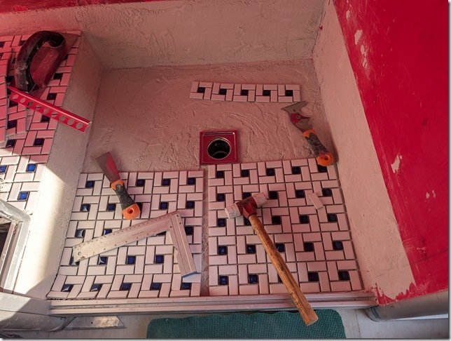 Then I moved onto the Shower floor and started the dry layup there.
 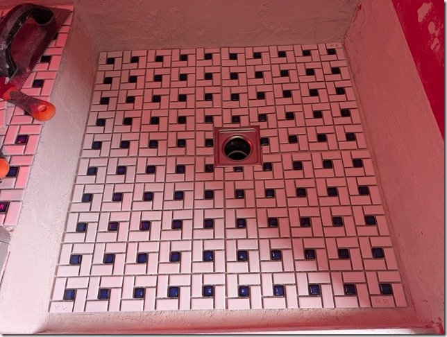 You can see how I needed to trim the tiles a bit along the edges of the square SS drain which I did so that the outer edges of the regular square spiral patterns would match up with the outer edges.
 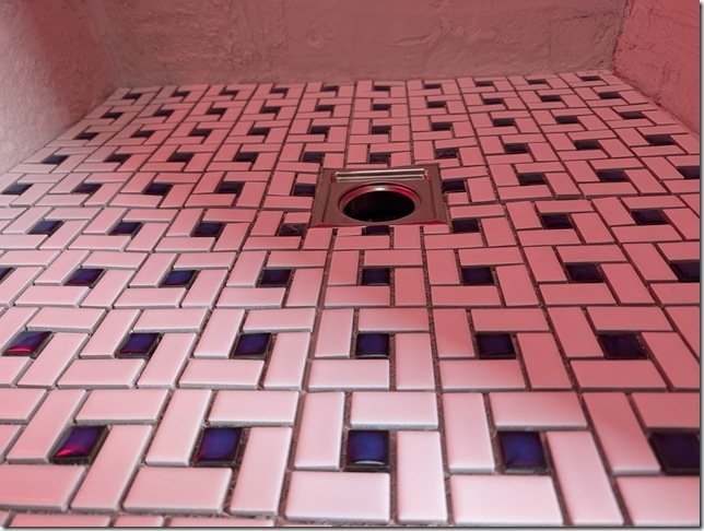 And it all slopes down from the edges to the drain.
 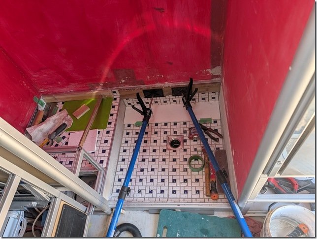 I thought it would look better to create a single upper edge surrounding the whole space so I put in some aluminium edging and tiled up to that along all the sides of the Shower and the Head floors and set them in place.
WALLS:
 For the walls I wanted to find the best combination of waterproof, easy to clean and good looking so I ended up going with these White tongue and groove PVC planks that are about 18cm / 7” wide with grooves molded in to look like narrower planks, and started cutting them to size.
But I thought that all White walls and ceiling would be too bland so I decided to create a horizontal band to break up the walls that would wrap all the way round and fill this with some of the Blue & White spiral tiles I had left over from doing the floor.  I picked up some aluminium edging meant to be used under tiles which you see propped up in the corner on the Right here and used that to make the transitions from tile to PVC planking. I taped off the top and bottom edges of the area for this band…………..
 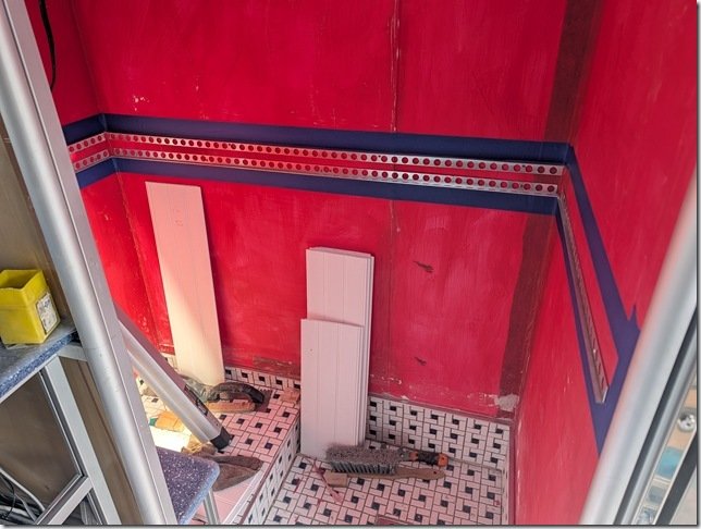 ………. and installed the AL transitions edging all round.
 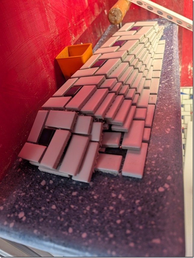 I had enough left over tile to cut these bands off the sheets and used that size to determine the width of the band.
 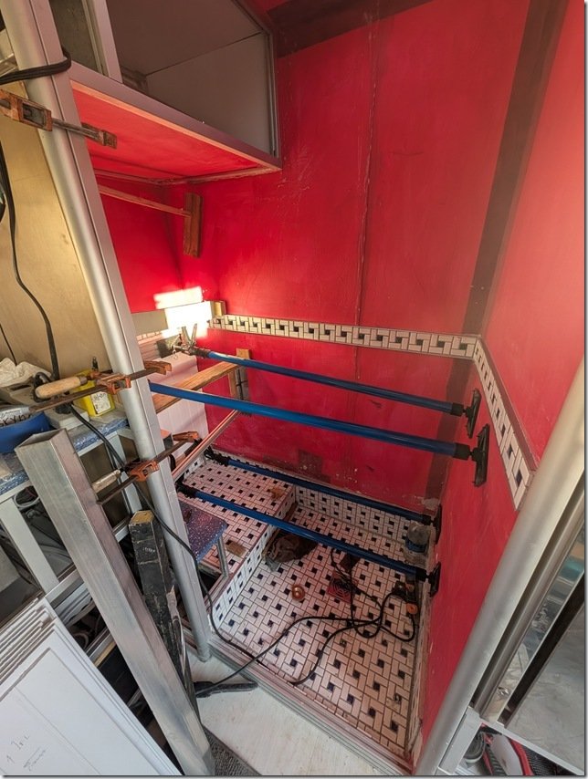 Worked out quite well and now time to put up all the PVC wall planks.
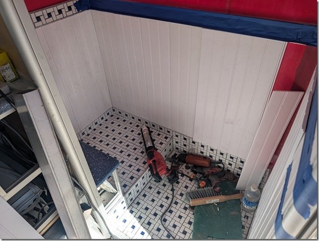 It was quite quick and easy to cut the 8ft long PVC planks to a nice fit between the top and bottom edges of the aluminium edging there the tiles start and stop.
And now time to use my trusty Milwaukee cordless caulking gun you see on the Left of the floor to put a nice thin line of White silicone adhesive/sealant along each tongue and groove and back of each plank. 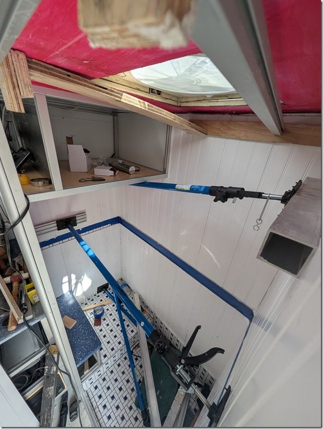 The cargo spreaders and some square aluminium tube cauls helped to hold the PVC planks flat while the silicone adhesive cured overnight.
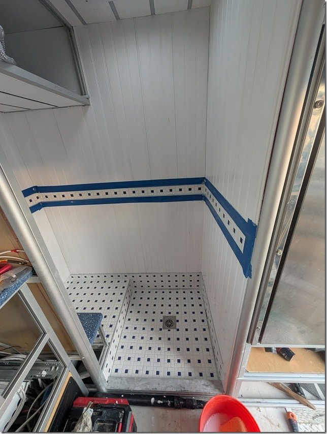 With the wall planks all done I could now grout all the tiles in this band and on the floors to finish the tiling.
 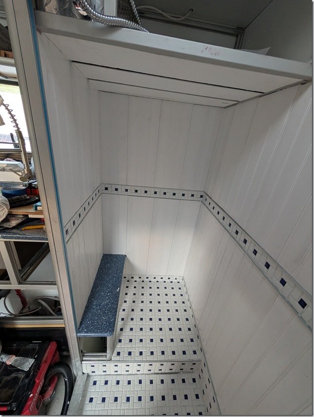 I did the ceiling with the same vinyl planking with a different pattern on it that I used for the ceilings in the rest of Lance. As with those other ceilings, I put in a strip of dimmable LED’s between each plank but more on that a bit later.
Et Voila! Lance finally has a not too bad looking Head and Shower.
LET THERE be LIGHT AND AIR!

We always like to have individual items do more than one thing and so we decided to install this 12V vent fan in the ceiling above the shower to provide both daylight and fresh air venting into the Shower & Head space. 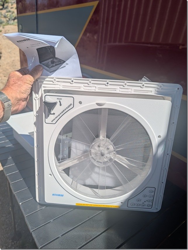 I’m not a big fan of the popular variations of the MaxFans that much of the RV and Van world seem to use and wanted to keep our overall vehicle height to a minimum and we’re at 2.9m / 9’ 5” right now with the solar panels and roof vent. So this Kohree vent unit seemed to check all our boxes.
This model also had a nice combination of both a manual override for raising and lowering the vent cover and a set of electric controls on the other corner of the fan as well as a hand held wireless remote.
It also has a temperature sensor to turn the fan on/off and a very quiet fan with 10 different speeds.
Other nice features are a built in rain sensor that automatically closes the vent though not much of a need when this is all inside that nice waterproof Shower.  I had purposely left this space up on the roof in front of the four 450Watt solar panels and their Super Strut rails so now time to cut the only hole in our otherwise seamless one piece roof.
Yikes!!!! 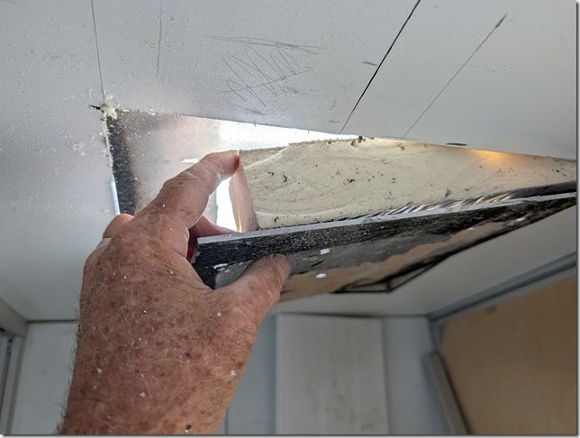 There are three thick aluminium plates in the roof of Lance, one for the top skin, the layer you can see here that forms the internal ceiling of the ambo box and then ……
 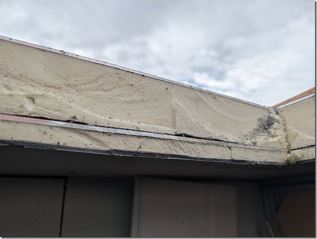 ……… the final layer of 5mm thick ACM that I installed for the ceiling surface below the additional layer of 20mm IPS foam insulation.
 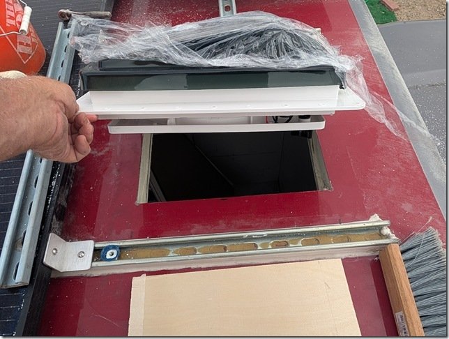 The vent dropped in just right.
 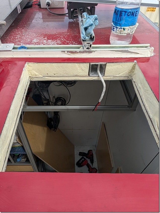 I used this 2×2” square AL ceiling beam for a conduit for the wires to power and control the fan.
 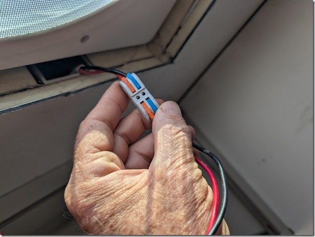 I’m a BIG fan of these WAGO wire connectors and have used them throughout the build. They worked well to connect these 12VDC power wires to the fan and then tuck nicely into that square AL tube.
 Checked everything for a good fit including this trim frame and then ….
 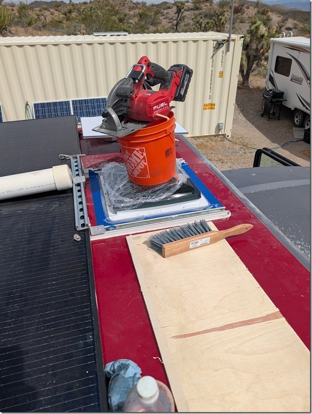 ………. bedded the vent into the roof with 3M 5200 sealant and some makeshift weights to let it cure overnight.
and MORE LIGHT!

As I mentioned earlier, I matched the ceiling in the Head & Shower to what I installed in the rest of Lance which are these planks of White solid vinyl with a nice grained texture and then put in strips of Black aluminium LED channel.
I will then adhere dimmable COB LED strips inside these AL channels and snap on the diffuser cover.
All fully water immersion IP68 rated so no problems in this wet area. 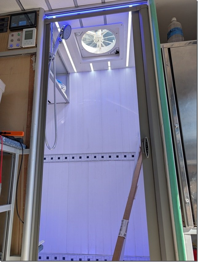 Worked out well to provide Goldilocks just right lighting both night and day.
 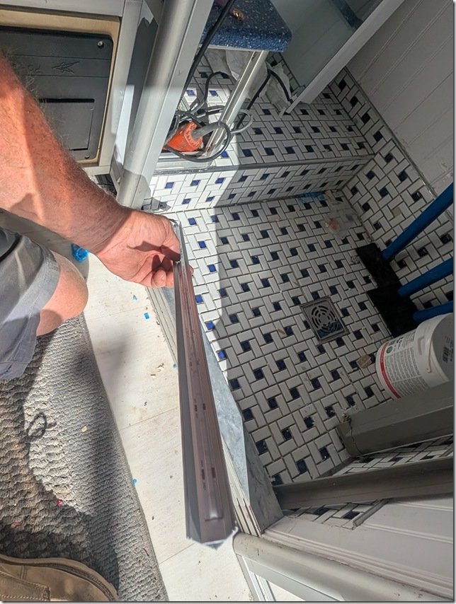 One last detail for those few times (so far) either of us needs to get up and use the Head in the middle of the night, I wanted also have some indirect low level lighting inside the Head & Shower area. So I installed some of these 45 degree angled aluminium extrusions in hidden areas such as under the door sill into the Shower you can make out below my hand and another under that little Blue shelf in the Head.
 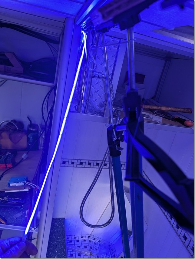 To help keep our night vision and add a bit of “ambiance” I used these Blue LED strips which are also dimmable to whatever level of Blue light you’d like.
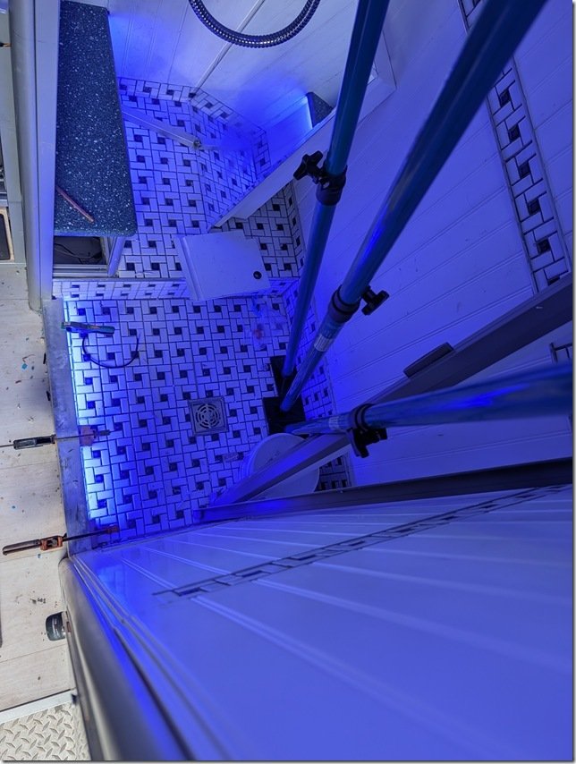 Testing out the LED strip tucked in below the door sill into the Shower.
DOORS!!!
After using Lance for over a year now with NO doors on the inside one member of the crew is eXtremely eXcited about having a DOOR on the Head!!! 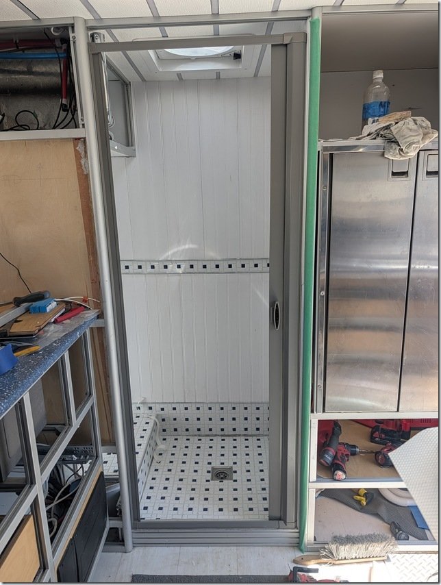 After some debate and research we decided to go with this retractable shower door that rolls up when OPEN like this
 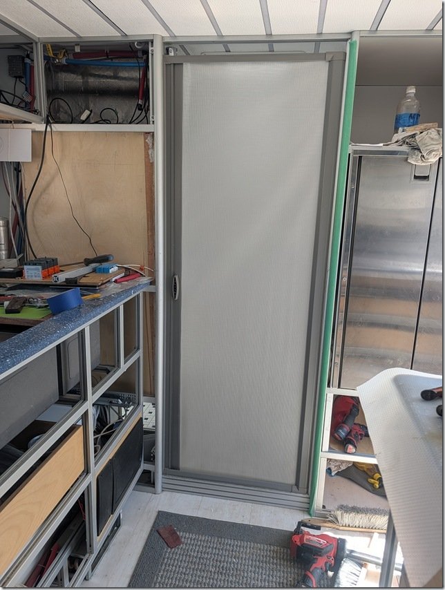 ….. and then rolls out to seal and CLOSE like this.
 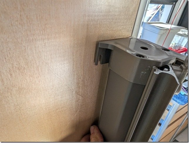 The flexible material rolls up on a spring loaded shaft hidden neatly inside this cassette that mounts to the left side of the door.
 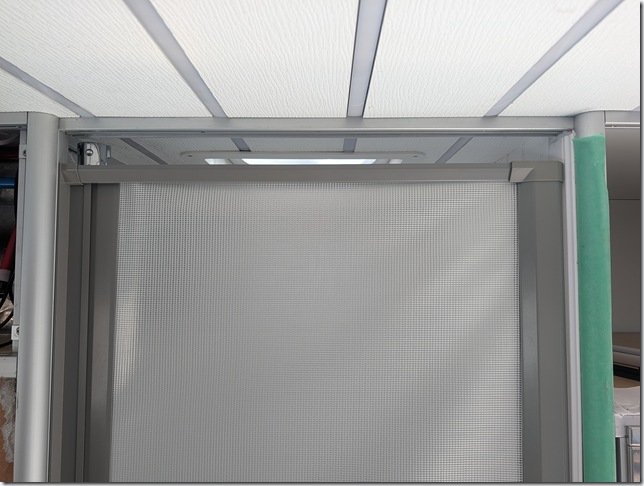 The “door” slides on tracks concealed inside the AL extrusions top and bottom and I left a small gap at the top to help with air circulation.
FINISHING TOUCHES:

To keep things dry inside this storage cupboard above the head, I glued in some sliding door AL tracks and cut some clear 6mm / 1/4” acrylic for the sliding doors. 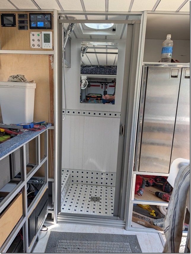 And then mounted this mirrored Medicine Cabinet on the rear wall to finish things off.
SHOWER FAUCET:
You c an’t have much of a shower with no water so along the way I installed this very nice adjustable hand held shower head that has a full shut off valve on the handle and ….
 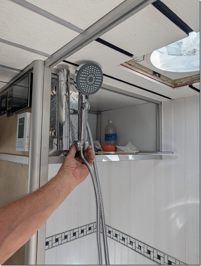 …… connected it to a thermostatic controlled mixing valve faucet. These are great for maintaining a whatever water temperature you set it to coming out of the shower head. The button allows you to turn the water on and off as you wish to conserve water and have it off when you want to wash your hair, shave, etc.
 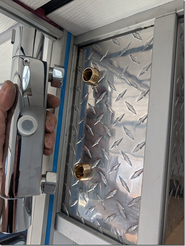 The SS cylindrical knob on the top end rotates to set the temperature and the one on the bottom controls the water flow volume.
To mount this I cut a sheet of 6mm / 1/4” thick aluminium diamond plate which fits just right into the slots of the 1” 1010 Series XAL framing. 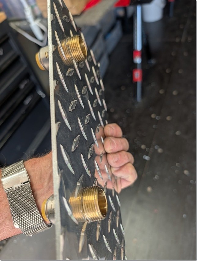 I drilled and threaded this plate to mount these two brass fittings for the thermostatic valve to attach to on the outside and push-connect fittings on the other side …………
  …… for the Hot & Cold water 1/2” PEX-A lines to attach to.
  The Yellow handles are shut off ball valves on each PEX water line for servicing or winterizing.
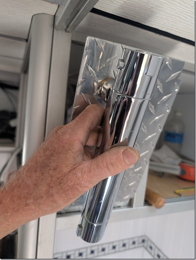 The whole assembly then fits securely into the slots in the XAL framing.
CONTROL PANEL:

Finally, to enclose this service bay area I built this temporary panel and with many of our controls for the systems in Lance mounted on it.
This is just a prototype I am trying out made out of scrap plywood with some of the switches, controllers and thermostats mounted in it. 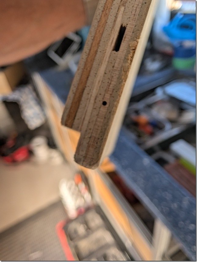 I cut this rabbet or tongue on the bottom edge that is a snug fit into the groove on the bottom length of XAL framing.
 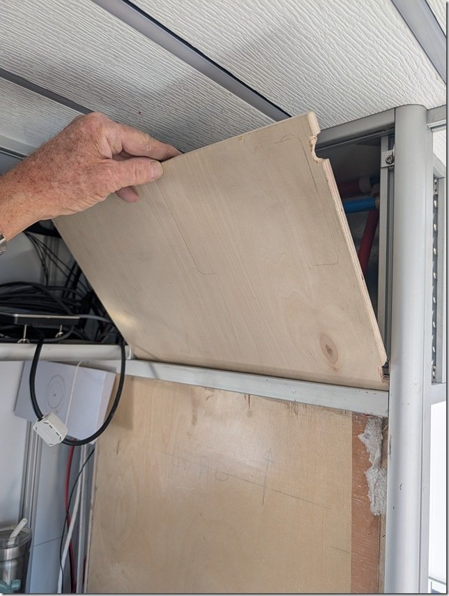 The way it works is that you first put the bottom tongue into the groove and then ……..
 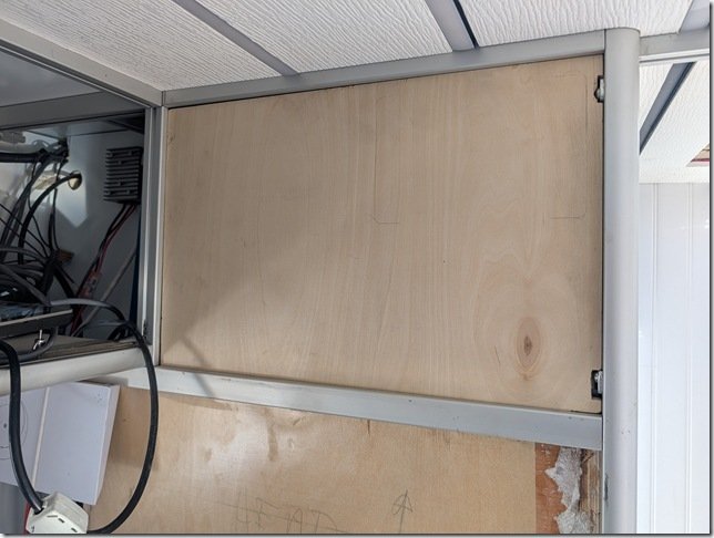 …………… tip the panel up into place.
 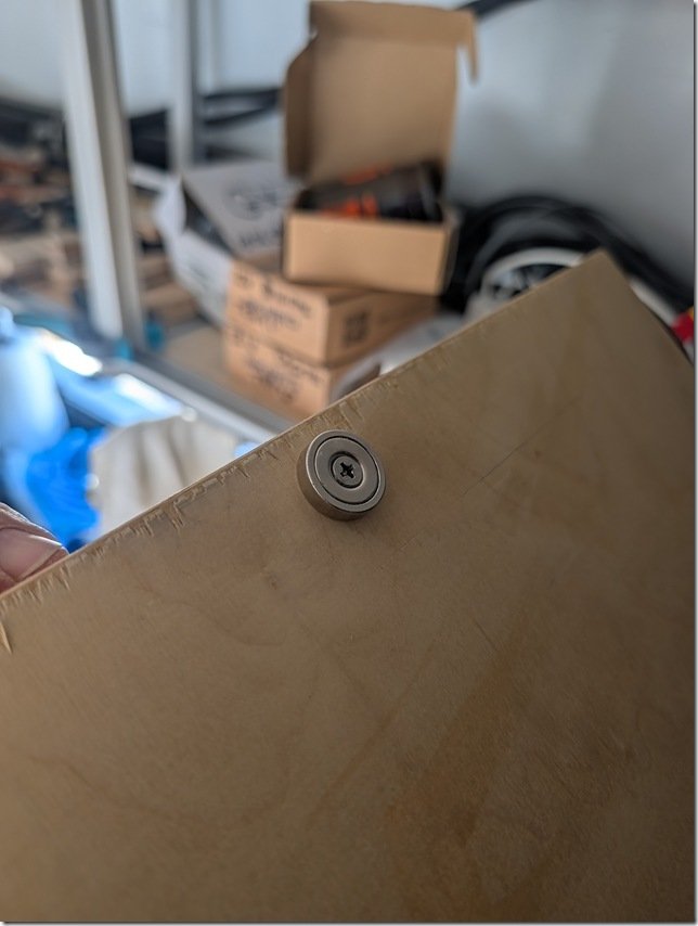 To hold this and likely all the panels in Lance securely in place, I’m trying out using these very strong round “donut” Neodymium magnets. This one is a 40 pounder, meaning it takes about 40 pounds of pull to remove. These magnets are available from less than one pound up to over one hundred.
 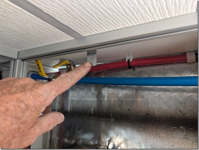 All the metal in Lance is aluminium which of course isn’t magnetic so cut a short 5cm/2” length of steel flat bar and drilled a 6mm hole in one end so I can bolt it to a T nut captured in the XAL slot on the back here. Worked out even better than I hoped and the panel snaps into place with a good “thud” and locks the whole panel tightly in place.
But I only need to reach behind it and push hard with my fingers to pop the panel forward and out. 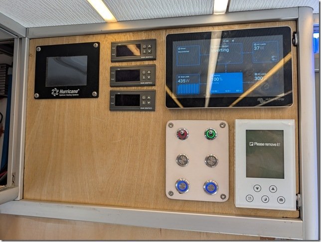 Here is what the panel looks like so far. White thermostat for the heated floors in the Head & Shower in the bottom right (currently turned off) and the Victron Cerbo GX touch display above it and switches for things like water pump, Starlink power and the thermostatic controllers for the heated main cabin floors over to the Left.
I will likely change the layout a bit and add a few more switches and meters, but it all works for now and we’ll try it out on our travels in the next month and see what other changes we might want to make.
And th th th thaaaaats all for this update folks.
Hope it was entertaining and of interest to you and that you’ll be back for the next update in a few weeks.
We are going to be out in Lance eXploring more of Beautiful BC for the next few months till we head off to Europe at the end of August so I’ll do my best to get the last few updates posted for you. Next big project that I’m not starting on is to build all the Cherry veneered drawer fronts, doors and interior panels that will should pretty much finish Lance’s build.
Don’t forget to add your comments and questions in the “Join the discussion” box below and enjoy your summer wherever you are.


 These two pallets are from Current Connected with four 420 Watt solar panels on the Left and then the Victron inverter/chargers, MPPT controllers and EG4 batteries on the Right. These are a bit fragile but they all arrived in perfect condition.
  I unboxed one of the EG4 12V 400Ah server rack batteries to check them out a bit closer and to get the exact dimensions so I can complete the XAL eXtruded ALuminium racks I’ve installed in Lance. There are three of these monster batteries that I’ll wire up in parallel to create our 12V 1200Ah House Battery bank which gives us a whopping 15.4kW of overall capacity. Even though we have gone mostly electric with all our systems other than diesel for our heating, our daily requirement will be much less than this but I’ve gone to this capacity so that we can stay remote for weeks at a time even with long periods of cloudy days with low solar output.
  These two Amazon boxes contain the new sink and induction cooktop for our new Galley aka Kitchen in Lance.
  This is the Empava 120V 1800 Watt two burner induction cooktop that Christine chose. It will be built into the countertop but can also be removed and taken outside to create our outdoor kitchen in hotter weather. Christine set this up here in the house and made dinner with it two nights ago and she gives it an enthusiastic two thumbs up! We both much prefer induction cooking after our experiences with it on Mobius.
  This is the 28 inch dual SS sink. It is a generous 245mm/10” deep as we both prefer big deep sinks.
  This one has some great features that extend its usefulness such as this wooden cutting board and a strainer that slide back and forth in the groove you can see at the top and bottom.
 Here is a quick screen grab that I hope helps you visualize the interior layout. Double sink in the Drivers Side Galley countertop up top and the induction cooktop on the Passenger Side.

 Pretty straightforward process; peeled off the protective plastic layer with the blue arrows and then starting laying down the 8 inch wide click-lock planks.
  It is not the recommended practice, but I’ve decided to install this finished flooring first and then put in the framing for all the cabinetry as this will create a much cleaner install of the XAL eXtruded ALuminium framing. We used this same type of industrial grade LVT planking in Möbius and were eXtremely happy with it so we stayed with what we know works.
  We
We Razz and Zoe have been eXtremely busy as well as you can see from this shot of what is at my feet as I type!


 The floors were made of this Lance Club sandwich that starts on the bottom with the 4mm AL floor plates of the original Horton ambo box, then a 3mm layer of rubber matt, a 13mm/ .5 inch layer of AL foil faced PIF R3 insulation topped with a layer or 4mm ACM.
  For those unfamiliar with it, PEX tubing is a cross-linked polyethylene pipe manufactured using extrusion method that creates infinite lengths of extremely strong and flexible tubing. It has been around for over 50 years and has largely replaced the use of copper and PVC pipes for plumbing in residential and commercial buildings. It is readily available in coils up to 500 feet and sizes from about 6mm/ 1/4” up to 2” with 1/2, 3/4 and 1 inch being the most popular.
  I have had great success using PEX for plumbing other projects over the years and it is pretty much the go to tubing for hydronic heated floors in any building. We used this for the floors in our previous boat Mobiüs and once you’ve had heated floors you never want to be without them again and this was one of the givens when we started to design Lance. I will also use PEX for all the plumbing of our hot and cold water systems in Lance so you’ll be seeing it quite often here as the build progresses.


 I had also ordered a box of these special aluminium heated floor transfer plates that are typically used in plywood based radiant floors but I wasn’t satisfied with the way they fit.
  Even after some judicial flattening with a hammer these plates just would not lay completely flat and created an air gap that would not have been as effective in transferring the heat from the PEX tubing into the surrounding AL flooring, and this would have also created a slightly non flat surface for the finished floors which was also not acceptable.
  It would have worked OK to just press the PEX into the grooves but I wanted to maximize the heat transfer so I used some thick 5 mil aluminium ducting tape and carefully pressed this into the grooves.
  ….. and that gave me the Goldilocks just right fit I was seeking.
 Once again my 3D modelling for Lance paid off by allowing me to get the just right layout of the lengthwise running PEX tubes.
  Once I had the spacing and layout all worked out I simply used the “Sweep” function in Fusion 360 to follow the sketch line and create the model of the tubing itself. The minimum bend radius of this 1/2” PEX-A tubing is 6 times the 5/8” OD so 3.75” and I increased this to 4.5” for a bit of safety and that’s why there are those round abouts as each run of PEX makes the U-turn to go back the other direction as you see here.
  With all that planning in hand I used some 1” wide blue masking tape to lay out the location of the 1” wide eXtruded Aluminium or XAL cabinet framing that will be bolted to the floor so that I could be sure that the PEX tubing would not interfere with this. You can see that I traced out the center line of the PEX tubing with a felt pen to help me position the router.
  I cut out this jig from some scrap 5mm ACM from the original build and used this to guide the base of the router to make this sweeping omega shape for the U-turns at each end.
  To make sure that the open end of the Omega shaped jig was the proper distance I made this short piece to press fit between the two legs of the jig and then marked two lines where the actual PEX tube center lines of each leg should be. This made accurately positioning the jig very quick and easy.
 Then with the outer edge of the base of the router pressed tightly against the inner edge of the jig I was able to guide the router bit along the just right track.

 Quick test fit using a short piece of the PEX tubing and I was ready to go.
  Reposition the jig for the next cut ……
  …….. rinse ……..
  ….. and repeat ……….
  There were a few places where the base of the larger Bosch router were too big so I built a smaller jig and
  ……used my cordless Milwaukee router to cut those grooves.
  Used the same jig and router to cut these grooves where the PEX tubing enters and exits into the external compartment where the diesel boiler will be.
  And that completed all the router work and all was groovy. (sorry, couldn’t resist)
  Next I peeled off the protective layer of plastic with all the blue lines and arrows, from the ACM floor and started to press in the AL ducting tape to line each groove.
  The AL ducting tape is eXtremely sticky on the back but I was able to fold each 3” wide length in half, peel off the paper backing ………..
 Then I could use a combination of my index finger and ..
  The end of one of my vacuum nozzles that conveniently had just the right radius to press the sticky AL ducting tape onto the sides of the grooves.
  For the radiused U-turns I used the same technique to insert the folded tape lengths into the groove and then sliced the outer edge so I could bend the tape over and stick it tight against the ACM.
  Putting my weight on the plastic roller worked well to get the tape very flat and well adhered to the ACM.
  Ta Daaaa! All done and ready for the PEX tubing to be pressed in place.
  Where the PEX tubing enters and exits the mid Drivers Side external cabinet I needed to come up with a way of protecting the PEX from the edges of the AL holes I had drilled through.
 With the help of my (headless) Beautiful Bride and my trusty sledge hammer we were able to feed the PEX back and forth into the grooves and then back
  …..into the compartment where I could slide on the other parts of the fittings and tighten them snuggly in place.
  Worked out very well.
  Final step was to put AL ducting tape over the top of all the PEX tubes and the floor is now ready for the final layer of 4mm ACM to go on top and that is where I will pick up tomorrow morning to start another week working on Lance.

 Going back to the beginning a bit, this is where we left off last week having installed all the PIF (PolyIso Foamboard) insulation and the ACM panels on the walks and ceiling.
  And going back ALL the way to January when we went and picked up Lance in Illinois, here is what the original floor and interior looked like.
  Prep work on the floor began with removing the vinyl diamond plate flooring and then the eXtremely recalcitrant aluminium track you see running down the center of the floor in the photo above. This track is what the collapsible Stryker ambulance stretcher rides on and locks it in place. For safety and security this 25mm/1” thick AL track is through bolted into the floor framing below with large high strength steel bolts.
 The floor material you see here is 13mm / 1/2” thick ACM that will make a great substrate to embed the 1/2” PEX tubing into the floor later to circulate the hot floor heating liquid through so I wanted to be able to reuse this huge continuous sheet. To do so I carefully cut through the ACM floor lengthwise along one side of the track’s slot using my cordless circular saw and a long straightedge to get a very straight edge that will later become a butt joint of the two halves in the new floor.
  You can see how clean and square an edge the carbide blade in the circular saw leaves on the ACM and will make for a smooth seamless transition between the two halves when I reinstall them later.
  The ACM flooring was through bolted to the 2” x 3” AL floor frames below but not glued in place so once I had all those bolts removed I could pry the ACM up to remove it.
 I was then able to flip each half of the ACM floor up as you see here.
  Several of the bolts fastening the ACM to the AL floor frames had sheered off when I was removing them so I brought out some of these Weapons of Mass Deconstruction to remove them.
  This shot as I’m removing one half of the floor gives you an idea just how large the original ACM flooring was. A single sheet about 4.25m / 14’ long by almost 2.4m x 8’ wide!
  So I spent several hours scraping off the tar matt in that rear DS corner to clean that all up.
  Final preparation for the new flooring began with trimming up the two halves of 1/2” ACM I had removed previously. In order to get a continuous straight tight joint down the middle I turned one half of the floor ACM end for end and resawed this edge to be perfectly straight.
  I dry fitted each half in place to get all the cut outs around the external storage compartments along each side and then slid the ACM halves back out and was finally ready to start installing the new flooring.
  First layer of the new flooring is this 1/2” thick PIF (PolyIso Foamboard) that is faced on both sides with AL foil.
  As you saw me do with the ACM above, I cut and fitted the PIF around all the compartment cut outs and soon had the first layer of the new flooring all in place.
  Next layer was the 1/2” ACM so I carefully laid that in place on top and used some lengths of 2×2” square AL tubing for straight edges to compress the ACM to the PIF and make the floor flat and seamless.
  That center joint between the two halves of ACM worked out very well as you can see here up at the front wall.
  I cut new pieces of 1/2” ACM for areas I had cut out the original external compartments and glued them in place. This new ACM is the same as the original, just has AL faces that are white.
  If
If The final layer before I can route the grooves for the 1/2” PEX tubing for the heated floors is a layer of new 4mm ACM. Pretty straightforward; 4×8’ sheets are trimmed to fit around all edges and then the protective plastic is peeled off the bottom surface.
  The same DAP/Weldwood Landau HHR contact adhesive you saw being used last week on the walls and ceiling is poured into the electric HVLP spray gun.
  Top and bottom AL surfaces are covered with a thin film of this contact adhesive.
  …… and with Christine’s help, carefully lined up and lowered the gooey panels into their final resting place as you only get one shot with contact adhesive that grips for good immediately.
  Which takes us back to the end were I began this week’s update so I’m going to leave off here for this week and pick up next.
Recent Comments