I appreciate your patience as I continue to try to catch up with posting updates here on my progress with the transformation of Lance from his start as a 2016 Kenworth T270 Medium Duty ambulance from a fire department in Wisconsin to an eXtreme RV or XRV for us to continue our explorations via our Land Yacht. I’ve got a few more updates to do but I just about have you up to date on all the various projects within Lance and this one will take you through the completion of the Head & Shower area inside Lance’s Hab/Habitat/Happytat ambo box.
Last month, May 2026, while I was still at our place down in the very southern tip of Nevada which we call “Road Runner Ranch”, I was able to finish building out the Head and Shower area in Lance.
* FYI, Christine and I are still sailors at heart so the Bathroom will always be the Head and the Kitchen will always be the Galley for us.
I drove Lance up to our place on Saturna Island mid May and am now working up here at finishing off the interior while we are up here through end of August.
Here is what I was able to get done before that drive;
To help with your orientation, this screen shot from my Fusion 360 3D model shows where the Head & Shower are located in the front DS Driver Side of Lance’s Hab/Habitat/Box which is on the far Right of this view. The Settee & table are at the opposite back end on the far Left with the Galley counters spanning both sides in the middle.
Note: You can click on any photo to enlarge it.
Here is what it looked like IRL (In Real Life) from the inside when I got started. That’s the SS Fridge/Freezer on the far Right, Blue DS Galley countertop peeking through on the Left and that’s the DS Front corner of the Hab in the far middle of this photo. The toilet will sit on top of the raised floor section and I’m getting ready to put in the the shower pan on the lower section of the floor that the blue cargo spreaders are resting on.
The framed in area above the Head will be a storage cupboard on the larger Right side portion and then the smaller space created on the Left will be a service area for plumbing and electrical which I’ll cover later on in this post. I started prepping the interior by gluing 1/2” Baltic Birch plywood on the XAL eXtruded Aluminium framing of the two walls you see here on the Left and Rear. I use these adjustable Blue Cargo Spreaders (from Harbor Freight) all the time and here they are helping apply pressure to the freshly glued in BB plywood panels to keep them flat and straight.
The small box protruding into the Head area on the bottom Left is the front end of the large middle exterior compartment you saw me filling up with all the plumbing and heating systems in the previous post. For maximum adhesion of the rigid foam Shower Pan I removed all the LVT vinyl floor planking that covers all the floor area inside Lance’s Happytat. To help with tiling the shower pan and getting the slope to the center shower drain just right, I bought a Vevor shower pan kit that is specifically made for this purpose and adds even more insulation to the shower floor. It is covered with a thin gray felt that grabs the thinsulate/mortar bedding compound I’ll be using to bed in the electric grid for the heated floor and the ceramic tiles. Very nicely designed bit of kit and the floor foam is cut in half with the felt glued on top to act like a hinge and made it much easier to press fit the floor into place after cutting it to size. You can see here how the area for the flange of the PVC drain is already pre-cast into the foam and you’ll also note the large circular recess surrounding it for bedding the drain flange into the floor. After checking that it all fit just right, I removed the foam pan, applied a silicone based adhesive with my cordless caulking gun (that I’m enjoying more ever time I use!), spread it out evenly with a notched trowel and pressed the floor pan back into place using my trusty cargo spreaders and some aluminium and plywood cauls to press it even and flat. It was difficult to see in the photos above but I also used 1/2” BB plywood to cover the wall between the Shower and the Fridge/Freezer compartment. I caulked all seams and corners with construction adhesive for additional sealing of those.
Next I put in this small bit of XAL framing to extend that exterior cabinet “bump” all the way to the inner edge of the Head raised floor. This will also create a handy storage area.
The black lines you see on the White ACM Aluminium Composite Material of the Head Floor is from me laying out the spacing for the heated floor electric grid you’ll see a bit later below. Now it was time to completely waterproof every surface inside the Head & Shower to ensure that there are no leaks in the future. I used the ever popular RedGuard and brushed it on all the surfaces.
After the first thin coat of RedGuard was on I went around and used more RedGuard to bed in some reinforcing felt that I cut into strips and pressed into all the corners and seams with more RedGuard. The drain area received several more coats of RedGuard as this will get the most traffic and potential for seepage. The pink colour is from the still wet RedGuard which quickly changes to Red as it dries fully. Et Voila!!
A very Red and very waterproof Head & Shower area. A bit messy but my 11cm/ 4 1/4” hole saw did a nice job of cutting this hole through all the layers of insulation and aluminium in the floor for the PVC drain to set into and exit out the bottom where it will connect to PVC pipe and on to the Gray Water tank. You can also see the 2 inches of insulation that are below the shower floor. I had some of this Blue Solid Surface acrylic material left over from doing the Galley countertops so I used this to create a nicely contrasting and durable shelf top on that bump out in the Head. This solid acrylic material is heavy but is very nice to work with; cuts easily and cleanly with regular carbide saw blades and router bits and then sands/files nicely to create a polished surface. I wanted to get this shelf installed before I started putting in the PVC planking that I’m going to use to cover the walls.
TOASTIE TOOTSIES!
As I mentioned in the previous post about our diesel powered Oasis Zephyr boiler, the rest of the floors inside of Lance are heated via the hot glycol (anti-freeze) pumped out of that boiler and flowing through the loops of 1/2” PEX-A tubing embedded into the insulated foam below the LVT vinyl plank flooring. But I wanted to be able to control the heated floors in the Shower & Head separately as it is always nice to have warm shower floors even in warm weather.
So I opted for another Vevor product, this heated mesh flooring kit that runs on 220VAC and has its own thermostat. The kit comes with this Orange plastic mesh which the Black heating cable gets attached to.
Also came with this every nice digital thermostat for controlling and reporting on the heated floors. This is the transition piece where the cable changes from the 220VAC power cable to the heated wire. As it is a larger diameter I routed a groove into the ACM flooring so this thicker diameter would sit flush with the floor surface and be better protected. The heated cable is one continuous length and you can not cut this so it took me a bit of planning to get the spacing right but all fit in very nicely and will keep our tootsies warm both when showering and sitting on the Throne!
There is also a temperature sensor that gets embedded in the floor and provides this data to the thermostat so it can maintain whatever floor temp you set. I put this inside a length of protective tubing and that’s the L shaped length you see here which then exits out the side wall and goes up to the thermostat. I put this sensor in this larger diameter tubing so I could remove and replace the temp sensor if it should ever fail. With all the heated cable and mesh in place I mixed up the epoxy thinsulate/mortar and spread out about a 13mm / 1/2” thick layer with a steel trowel and smoothed it all out. Didn’t get a photo when it was done so this is part way through the process. Finally ready to start tiling!
TILE TIME:
We found this Blue & White Spiral pattern ceramic tile online and both really liked it so that’s what is going on the floors. Comes in these larger approximately one square foot sheets with individual tiles glued to a mesh on the back which makes handling and setting them much easier. Laying out this type of spiral pattern is a bit tricky and takes some planning to make sure all the corners and joints line up and maintain the pattern. If you look closely you’ll see that you can only get a straight line for butting up against corners or lining up sheets in one place along the larger square formed by each spiral.
I created a quick 3D model (of course!!) to help plan the layout to get all the corners and seams to match up. Where I needed to cut some of the tiles such as around the drain, my trusty Dremel tool with a diamond cutting wheel worked like a charm to get nice straight cuts and smooth edges and you can maybe see along the bottom edge for this sheet I’m trimming square here. It had been a Looooooooong time, think decades, since I last did any tiling so I started with the floor in the Head as it will largely be covered by our Joolca “Gotta Go” separating toilet to cover any learning errors, but it all turned out quite well I thought. Then I moved onto the Shower floor and started the dry layup there. You can see how I needed to trim the tiles a bit along the edges of the square SS drain which I did so that the outer edges of the regular square spiral patterns would match up with the outer edges. And it all slopes down from the edges to the drain. I thought it would look better to create a single upper edge surrounding the whole space so I put in some aluminium edging and tiled up to that along all the sides of the Shower and the Head floors and set them in place.
WALLS:
For the walls I wanted to find the best combination of waterproof, easy to clean and good looking so I ended up going with these White tongue and groove PVC planks that are about 18cm / 7” wide with grooves molded in to look like narrower planks, and started cutting them to size.
But I thought that all White walls and ceiling would be too bland so I decided to create a horizontal band to break up the walls that would wrap all the way round and fill this with some of the Blue & White spiral tiles I had left over from doing the floor. I picked up some aluminium edging meant to be used under tiles which you see propped up in the corner on the Right here and used that to make the transitions from tile to PVC planking. I taped off the top and bottom edges of the area for this band………….. ………. and installed the AL transitions edging all round. I had enough left over tile to cut these bands off the sheets and used that size to determine the width of the band. Worked out quite well and now time to put up all the PVC wall planks.
It was quite quick and easy to cut the 8ft long PVC planks to a nice fit between the top and bottom edges of the aluminium edging there the tiles start and stop. And now time to use my trusty Milwaukee cordless caulking gun you see on the Left of the floor to put a nice thin line of White silicone adhesive/sealant along each tongue and groove and back of each plank. The cargo spreaders and some square aluminium tube cauls helped to hold the PVC planks flat while the silicone adhesive cured overnight.
With the wall planks all done I could now grout all the tiles in this band and on the floors to finish the tiling. I did the ceiling with the same vinyl planking with a different pattern on it that I used for the ceilings in the rest of Lance. As with those other ceilings, I put in a strip of dimmable LED’s between each plank but more on that a bit later.
Et Voila! Lance finally has a not too bad looking Head and Shower.
LET THERE be LIGHT AND AIR!
We always like to have individual items do more than one thing and so we decided to install this 12V vent fan in the ceiling above the shower to provide both daylight and fresh air venting into the Shower & Head space. I’m not a big fan of the popular variations of the MaxFans that much of the RV and Van world seem to use and wanted to keep our overall vehicle height to a minimum and we’re at 2.9m / 9’ 5” right now with the solar panels and roof vent. So this Kohree vent unit seemed to check all our boxes.
This model also had a nice combination of both a manual override for raising and lowering the vent cover and a set of electric controls on the other corner of the fan as well as a hand held wireless remote.
It also has a temperature sensor to turn the fan on/off and a very quiet fan with 10 different speeds.
Other nice features are a built in rain sensor that automatically closes the vent though not much of a need when this is all inside that nice waterproof Shower. I had purposely left this space up on the roof in front of the four 450Watt solar panels and their Super Strut rails so now time to cut the only hole in our otherwise seamless one piece roof.
Yikes!!!! There are three thick aluminium plates in the roof of Lance, one for the top skin, the layer you can see here that forms the internal ceiling of the ambo box and then …… ……… the final layer of 5mm thick ACM that I installed for the ceiling surface below the additional layer of 20mm IPS foam insulation. The vent dropped in just right. I used this 2×2” square AL ceiling beam for a conduit for the wires to power and control the fan. I’m a BIG fan of these WAGO wire connectors and have used them throughout the build. They worked well to connect these 12VDC power wires to the fan and then tuck nicely into that square AL tube.
Checked everything for a good fit including this trim frame and then …. ………. bedded the vent into the roof with 3M 5200 sealant and some makeshift weights to let it cure overnight.
and MORE LIGHT!
As I mentioned earlier, I matched the ceiling in the Head & Shower to what I installed in the rest of Lance which are these planks of White solid vinyl with a nice grained texture and then put in strips of Black aluminium LED channel. I will then adhere dimmable COB LED strips inside these AL channels and snap on the diffuser cover.
All fully water immersion IP68 rated so no problems in this wet area. Worked out well to provide Goldilocks just right lighting both night and day. One last detail for those few times (so far) either of us needs to get up and use the Head in the middle of the night, I wanted also have some indirect low level lighting inside the Head & Shower area. So I installed some of these 45 degree angled aluminium extrusions in hidden areas such as under the door sill into the Shower you can make out below my hand and another under that little Blue shelf in the Head. To help keep our night vision and add a bit of “ambiance” I used these Blue LED strips which are also dimmable to whatever level of Blue light you’d like.
Testing out the LED strip tucked in below the door sill into the Shower.
DOORS!!!
After using Lance for over a year now with NO doors on the inside one member of the crew is eXtremely eXcited about having a DOOR on the Head!!! After some debate and research we decided to go with this retractable shower door that rolls up when OPEN like this ….. and then rolls out to seal and CLOSE like this. The flexible material rolls up on a spring loaded shaft hidden neatly inside this cassette that mounts to the left side of the door. The “door” slides on tracks concealed inside the AL extrusions top and bottom and I left a small gap at the top to help with air circulation.
FINISHING TOUCHES:
To keep things dry inside this storage cupboard above the head, I glued in some sliding door AL tracks and cut some clear 6mm / 1/4” acrylic for the sliding doors. And then mounted this mirrored Medicine Cabinet on the rear wall to finish things off.
SHOWER FAUCET:
You can’t have much of a shower with no water so along the way I installed this very nice adjustable hand held shower head that has a full shut off valve on the handle and …. …… connected it to a thermostatic controlled mixing valve faucet. These are great for maintaining a whatever water temperature you set it to coming out of the shower head. The button allows you to turn the water on and off as you wish to conserve water and have it off when you want to wash your hair, shave, etc. The SS cylindrical knob on the top end rotates to set the temperature and the one on the bottom controls the water flow volume.
To mount this I cut a sheet of 6mm / 1/4” thick aluminium diamond plate which fits just right into the slots of the 1” 1010 Series XAL framing. I drilled and threaded this plate to mount these two brass fittings for the thermostatic valve to attach to on the outside and push-connect fittings on the other side ………… …… for the Hot & Cold water 1/2” PEX-A lines to attach to. The Yellow handles are shut off ball valves on each PEX water line for servicing or winterizing.
The whole assembly then fits securely into the slots in the XAL framing.
CONTROL PANEL:
Finally, to enclose this service bay area I built this temporary panel and with many of our controls for the systems in Lance mounted on it. This is just a prototype I am trying out made out of scrap plywood with some of the switches, controllers and thermostats mounted in it. I cut this rabbet or tongue on the bottom edge that is a snug fit into the groove on the bottom length of XAL framing. The way it works is that you first put the bottom tongue into the groove and then …….. …………… tip the panel up into place. To hold this and likely all the panels in Lance securely in place, I’m trying out using these very strong round “donut” Neodymium magnets. This one is a 40 pounder, meaning it takes about 40 pounds of pull to remove. These magnets are available from less than one pound up to over one hundred. All the metal in Lance is aluminium which of course isn’t magnetic so cut a short 5cm/2” length of steel flat bar and drilled a 6mm hole in one end so I can bolt it to a T nut captured in the XAL slot on the back here. Worked out even better than I hoped and the panel snaps into place with a good “thud” and locks the whole panel tightly in place. But I only need to reach behind it and push hard with my fingers to pop the panel forward and out. Here is what the panel looks like so far. White thermostat for the heated floors in the Head & Shower in the bottom right (currently turned off) and the Victron Cerbo GX touch display above it and switches for things like water pump, Starlink power and the thermostatic controllers for the heated main cabin floors over to the Left.
I will likely change the layout a bit and add a few more switches and meters, but it all works for now and we’ll try it out on our travels in the next month and see what other changes we might want to make.
And th th th thaaaaats all for this update folks.
Hope it was entertaining and of interest to you and that you’ll be back for the next update in a few weeks.
We are going to be out in Lance eXploring more of Beautiful BC for the next few months till we head off to Europe at the end of August so I’ll do my best to get the last few updates posted for you. Next big project that I’m not starting on is to build all the Cherry veneered drawer fronts, doors and interior panels that will should pretty much finish Lance’s build.
Don’t forget to add your comments and questions in the “Join the discussion” box below and enjoy your summer wherever you are.
As we all head to the exit of 2025 I will continue to summarize the progress in various key systems and areas on Lance over the past few months.
This week I’ll bring you up to date on where the Galley is at so far.
Easily one of the most used and most important areas for our day to day live in Lance and our 10,000 + mile “maiden voyage” this past summer proved that our design worked well as we used it during that two month test drive. We prioritized large areas of open countertop, dual deep sink, induction cooktop and large fridge and freezer and you can see the basic layout from the 3D model screengrab here.
GALLEY COUNTERTOPS:
Here is what it looked like as of the beginning of June, just before we hit the road to the East Coast of the US. This is looking forward so Drivers Side DS on the Left and Passenger Side PS on the Right. Entry door into the Hab (Habitat/box) is on the upper Right with the large vertical door 10 cubic foot Fridge/Freezer on your Right as you enter.
Deep double sink being undermounted to the 25mm/1” solid surface acrylic countertop.
Lots of options for water at the sink; hot/cold adjustment at the base of the faucet with both a large flexible rinsing hose with its own nozzle & lever and then an independently controlled rotating spigot. To the Right of the main faucet is an ultra purified drinking water nozzle that has water that has been put through a full Acuva UV treatment to remove any possible remaining particles after ……….
……… it comes out of the main filtration which is handled by this triple set of progressive main filtration that all our potable water goes through.
We have eXcellent water pressure running about 65PSI thanks to this Kohree 7GPM pump. All the water system equipment is located in the externally accessed compartment that is midway along the DS.
On the PS of the Galley there is more countertop and our 2 burner induction cooktop that is eXtremely efficient and a joy to cook on. This cooktop fits snugly in the countertop cutout so it can be easily lifted out and plugged in outside when we want to cook out there.
The vertical extruded aluminium XAL on the Right here is the linear actuator for the PS Front corner of the Queen Bed lift system. Underneath both countertops it is all drawers as we find these much more efficient to use than cupboards and overall we have more than 20 drawers inside of Lance.
GALLEY DRAWERS:
I have always preferred dovetail joints for all drawers given their superior strength that stands up for decades of use and I think they look great too and so that’s what we went with for Lance. I was going to do this all myself but with almost a hundred dovetailed corners to do and SO many other jobs demanding my time and attention I decided to job this out. I found a fabulous company to work with called Barker Doors who offer a service using CNC (Computer Numeric Control) machines to custom cut all your drawers. I had all the drawers fully modeled in Fusion 360 so it was easy for me to send them these files with all the exact measurements I needed and they cut all the 5/8” Baltic Birch plywood to size for all the sides and the bottoms and then CNC cut all the dovetails. In the end this all worked out to cost less than I would have paid for just the Baltic Birch plywood and drawer slides so I was super happy with how this all worked out and I can recommend Barker Doors to anyone VERY strongly. They shipped all the pre-cut drawers to me as flatpacks like this so the whole shipment of all the drawers was not too large and they were all very well shrink wrapped and carefully boxed up so they arrived with no damage at all. They also offered a great prices on the the top quality Blum undermount ball bearing drawer slides I wanted so it all came as a single order which made my life easier.
Mounting more than 40 drawer slides to the XAL framework was very straightforward but time consuming to get them all exactly parallel and lined up. and some required a bit of Houdini moves to hold in place and tighten up. Next, I set up a little workbench on top of the PS Galley counter to assemble each drawer. Each set of dovetails only required a few drops of wood glue and they went together very well with two bar clamps and some taps with my little hammer to get the joints to fit together all the way. The dovetails were so precise that every drawer went together perfectly square and were solid as a rock. The Blum drawer slides required two slots in the bottom of each rear drawer side so I cut those out next and then I mounted to the Orange locking hardware to the bottom of the front corners. These are where the drawer slides clip into the drawer and make it very easy to lift out a drawer at any time. It’s a great system! Installing each drawer was now a simple process of pulling out each drawer slide………. ………… setting the pins in the rear of each drawer slide into the corresponding holes I had previously drilled and pushing them closed till they clicked in place. Et Voila! We’ve got drawers! Sad to say that I wasn’t able to get this done before we left on our big summer adventure so we REALLY appreciate having these now! I wanted all surfaces of these drawers to have a tough durable finish and decided to go with this two part Rubi Monocoat finish that you put on by hand with cloths rather than brush or spray. Hand rubbed finishes have always been my favorite and while this was a new one for me I was eXtremely pleased with the end result and the whole process of applying it. It was a bit laborious and a good workout but a very satisfying process for me. Difficult to see in photos but the Baltic Birch plywood came out with a glowing warm colour and a very tough finish that is also very easy to reapply in the future. To reduce the loss of usable space under the sinks I used these low profile P-traps which have turned out to work very well. and only required a small cut out on the rear of the two under sink drawers to clear nicely.
GALLEY CEILING & COB LED LIGHTING
Onwards and upwards I turned my attention to the ceiling of the Galley. It took a LOT of research to find the Goldilocks material for the ceiling but I finally found this White wood textured PVC trim molding material that checked all the boxes of light, easy to clean and attractive. It comes in 6” wide 8ft long planks and was very easy to work with. For lighting, I decided to use COB (Circuit on Board) LED strip lights which I set inside lengths of 20mm wide black aluminium U channel which I ran in between each of the White PVC ceiling planks. I like these newer COB strips for two reasons; they provide an uninterrupted line of light rather than individual points of light in the regular LED strips and they can be adjusted from about 2200K (very warm amber) up to 6500K (daylight white). In the past, SMD LED strips you have to chose a specific colour temp and they often have 60–120 LEDs per meter (≈1.5–3 LEDs per inch) whereas these COB lights have hundreds of micro‑LEDs tightly together, giving continuous light with no visible dots of light. Once I had the layout done and the strips of PVC and AL channel cut to length, the process went quite quickly. I could apply the construction adhesive to each plank and AL channel and press them up into place and then use my super handy cargo jacks and some scrap lengths of XAL to press these all up against the ceiling so they ended up flat and aligned. You can buy the COB LED lights in 20 meter rolls which you then cut to the lengths you want and solder three wires to the copper strips underlying the Yellow COB light strips. Takes a bit of practice to get these tight solder joints without any cross connections but all went pretty well after a few practice solders. Then I twist the wires to help reduce any electrical interference and slide a clear tube of heat shrink tubing over the joints and shrink them in place for a nice clean and protected connection.
Each of the LED strips have self adhesive on the back so you just peel off the protective wax layer and press these into the AL channel. I purchased the Black AL channel with frosted clip in covers so once I had the COB LED light strips glued in place and wired up ………… ……………. I could now press these clear covers in place. Here’s the result at about 6000k. These LED light strips are also fully dimmable so you can adjust both the colour temp from warm to cold white and from off to full almost daylight brightness.
We are very pleased with the end result.
Yet to come is the making of all the fronts to these drawers where I will get to use the fabulous 125 year old Cherry that my dear friends Colin, Rick and Sherry gifted us with but that probably won’t be until we get back here next year from our trip down to Baja so due stay tuned for all of THAT!
My sincere thanks for taking your valuable time to read these updates and join us on our adventures. Please leave your questions and comments in the Join the Discussion box below and hope to see you here again next week.
Hope all my American friends and family are wrapping up a great US Thanksgiving weekend. Christine has been back in Ft. Lauderdale for the past ten days enjoying some much needed Gramma time with our TEN year old Grandson Liam, seen here with his Dad Tim working on a new puzzle. As well as visiting dear friends of many years like Kathleen. Lucky me, while I can’t be there this time I often get to spend time with BOTH of these Gorgeous Galls. The pups and I have been holding down the fort here on Road Runner Ranch in Southern Nevada where the temps have started to drop and so Razz has taken to sunning himself on the solar panels for some extra warmth and seems like a good segue into today’s Lance progress update post on ……………………….. you guessed it; Solar Panels.
Living the nomadic and remote life that we always have, we are big fans having solar power be the primary source for all our daily electrical needs, which are quite extensive. On our boat Mobius we had factored solar panels into the design from the beginning and were able to have 16 large panels on three different roof surfaces on that boat such as these eight panels on the upper Pilot House roof. And here on Road Runner Ranch we have 18 solar panels in two banks, this one just set against one of our 40 foot shipping containers and the others you can see Razz laying on above. These keep our big EG4 Wall Mount 15kW battery charged up every day and running this through our EG4 6000XP Inverter/Charger provides all our electrical power for day to day life here. This is where the time I spent meticulously building Lance in a 3D model using Fusion 360 pays off. I could create a model for each of the different solar panels that I was considering and see how they would fit onto Lance’s roof and on the framing.
With much less surface area available for mounting solar panels on Lance’s rooftop I wanted to fit the maximum amount of solar output as possible and played around with lots of different solar panel models to get the Goldilocks combination that would fit. Over the years I have found it works best to design the overall electrical installation as a complete system because there are a lot of different pieces to this puzzle and they are all very interconnected not just electrically but also features and dependencies. I created 3D models for all of these components as well and you can see most of the components here in the Electrical Cabinet on the front Driver Side corner of Lance’s Hab/Box. There is a LOT to unpack here so I’ll cover the electrical system in a future post and get into all the details then for those interested.
After much deliberation and testing in the model, I decided to go with four SilFab 420 Watt QD panels which I purchased from Current Connected almost a year ago now. I was able to get these all installed this past May in time to help power us on our marathon maiden voyage with Lance driving out to Portland Maine and back this summer. For those interested you can see all the specs of these panels here and of course with the march of time since there would now be even higher output panels but we’ve still ended up with 1680 Watts of solar power and it has been more then enough to keep us fully powered all the time.
We do have additional sources of electrical power such as this 320 Amp 12V 3.8kW alternator on Lances Paccar/Cummins engine that can provide up to 4k of power anytime that engine is running. However on our summer test run I had not completed the installation of the Arco Zeus smart regulator so the alternator wasn’t working that whole trip and the solar kept our batteries filled the entire time so that was a pretty good testament as to how well the solar was working. I decided to use 10 foot lengths of galvanized Super Strut to mount the solar panels on Lance’s roof. I would have preferred to use aluminium Super Strut but the delivery times would not have been in time for me to get the solar panels mounted before our trip so I went with galvanized steel and they have worked out vey well. I laid them out as you see here, two lengths on each side and two down the middle. I added additional 4 foot lengths of Super Strut so that I would have a mounting system for the whole 14 foot length of Lance’s roof for mounting any additional items in the future. I kept the mounting very simple as well by cutting pieces off a length of 2” aluminium L bar, drilling two holes in each one for the mounting bolts, and using the very handy Super Strut M8 threaded inserts to bolt them solidly to the lengths of Super Strut. Quick, strong, simple; what’s not to like?!! I then made up the cables using extra UV rated cables, Red for the positive and Black for negative and crimping the MC4 twist lock connectors that are the most commonly used for solar panel wiring and which I’ve used a lot in previous projects so I have all the specialty tools, crimpers, etc. some of which you see here in the photo. To fasten the brackets to the solar panel frames themselves I inserted aluminium M6 threaded Riv-Nuts into holes I drilled into the vertical AL frame on the solar panel and then used this tool which compresses the threaded inserts and locks them to the frame. End result looks like this. One bolt vertically to fasten to the Super Strut and one horizontal to bolt into the solar panel frame.
For those wondering, I fastened the lengths of Super Strut to the roof using Loctite 8X PL Premium Fast Grab which is supposed to be 8 times stronger than traditional construction adhesives which I’ve used before. Probably overkill but you certainly don’t want solar panels flying off the roof when running down the highway at 70 miles an hour! To prevent any pooling of rainwater between the surfaces of the roof and the Super Strut I caulked all the edges with 3M marine sealant which I have LOTS of experience with on our previous boats. So everything fully sealed and eXtremely well fastened to the roof. Solar panel output drops off significantly with the rise in temperature of the panels, the irony of which isn’t lost on me, so I left this 4” gap where the two panels down each side meet up. This along with the 2+ inch space between the panels and the roof keeps them as well ventilated as possible and the efficiency of their output was very good even in the 40C/105F days we had several times on the trip AND while I was installing these panels! Talk about a cat on a hot tin roof! Ouch! To make it a bit easier to run the cables AND give me a wee bit of shade, I was able to remove the inner brackets and use the outer ones like a hinge and prop up one lengthwise pair of panels while I ran the cables. I ran the eight cables for all four solar panels to converge at this point on the front DS corner as this puts it directly overtop of the Electrical Cabinet below where they need to go and thus provides the shortest cable run for least voltage drop. I drilled the only hole in the roof for this but it was a BIG one as you can see and then I used more 3M 5200 to seal a short length of 2” PVC pipe as a safe conduit through the roof for these and all other cables in the future. The red square you see on the bottom is 3M VHB Very High Bond two sided tape which is a fabulous product for gluing almost anything to anything and it never comes off. PVC box now glued down to the roof over that PVC pipe and the cables run non stop down into the Electrical Compartment below.
Each solar panel needs to have a shut off so I used these DIN rail mini circuit breakers to do that and provide over current protection.
I use threaded glands, the black things you see here and above, to give each cable a watertight entry into all junction boxes. This is what it looked like inside the Electrical Compartment where the cables pass through. The output of solar panels is a much higher voltage than the batteries and needs to be regulated to different charging stages to properly charge the big LiFePO4 Lithium EG4 batteries in Lance so the output of the solar panels goes through a MPPT controller which looks after all of this. Although it isn’t common, the most efficient setup is to have a dedicated MPPT controller for each panel and so that’s how I’ve always built our solar systems. Those are the four Victron Blue boxes you see on the upper Right here. It’s a bit of electrical spaghetti and took a bit of time to route and connect all these cables but keeps all the wiring very well contained in the wire ducts like the one running vertically up the far Right side and will have a cap that snaps onto those fingers you see here. Final cabling is to take the output from each MPPT controller and connect them to the main 12VDC electrical bus bars which are the silver coloured bars you see running up on the far Right here. If you look closely you can see two Red and two Black cables connected together at the top and then the other four below so now all the power from the solar panels is connected into the 12VDC electrical circuit.
And here’s what Lance’s 1680 Watts of solar roof looks like.
The extra length of Super Strut has already come in handy for my temporary for now mounting of our Starlink dish and the 4” PVC tube running down the middle for storing long lengths of material I like to have for ongoing projects while we’re on the road. Go ahead and tell me you’re surprised?!?!
Did I mention that we LIKE solar panels???
And that wraps it up for this weeks progress update, hope it was informative and enjoyable and let me know what you think in the “Join the Discussion” box below.
As this recent holiday has reminded me I am indeed one eXtremely fortunate fellow with SO much to be thankful for, not the least of which is YOU, for the time you choose to take out of your busy schedule to read and comment here and join us on this latest adventure of the Ambo Nomads.
I’ll be back again next week with the next installment and hope you’ll join me again for that.
Ciao for now,
Wayne and “Sunny Boy” as he tells me he now likes to be called.
You might say that my world has gone to the dogs as Christine is back in Florida getting in some much needed Gramma time with our Grandson Liam, who somehow just turned TEN last week. Yikes! How did THAT happen?!?!?!? So here on Road Runner Ranch it is down to us Three Pupsketeers, Razz, Zoe and me, but we’re doing well and enjoying being surrounded by the beauty here in Southern Nevada.
Some of you may remember that the last post I did with updates on the work on Lance’s transformation was called “Mini-Split = Major Step Up: XRV Lance Update 4 May, 2025” May was a Looooooong time ago now so you may want to click on that link if you’d like a refresher.
Quite a lot of progress has happened with Lance’s transformation during the six months since that last post and I’ll do my best to cover as much as I can here in the coming weeks. To get started I’ll pick up where that update left off and catch you up on what happened between then and June 10 when we took left our place here in Nevada in Lance bound for Portland Maine for the June 21st wedding of my niece Julia to her beau Ben.
In the weeks to follow I will try to post once a week, usually on Sundays, providing updates on the work I’ve done on the different systems such as cabinetry, all the dovetail drawers, the Electrical Cabinet, rooftop solar panels and so on.
So grab a tasty beverage and a comfy seat and let’s get back to where we left off with that air conditioner/heater Mini-Split system you last saw in May.
Mini-Split is Fully Functional!
As per the title of that May 4th post, I had just finished quite literally shoehorning the exterior half of the Mini-Split unit up into the barely big enough space between Lance’s ambo box and the Kenworth frame.
And I’m very happy that I can start this week’s update with the news that I have since finished installing the Mini-Split and it is working even better than we had hoped. For those interested in the details, this is the make and model Mini-Split we decided on. It is a 9k BTU capacity “Pioneer Diamante Ultra” that is one of the most efficient models they make rated at 23.5 SEER for those who know that system. These type of two part aircon/heating systems are referred to as Mini-Splits because they consist of two parts; the outside condenser/compressor and the inside air handler evaporator. If you check out the basic features here this model provides both cooling in up to 131F/55C outside temps as well as heating when it gets down to from –13F/-25C. 9000 BTU is more than we need but the smallest model I could find so just means it won’t take much run time to keep the inside of the “Hab” as we have come to call the Habitat or Box or living quarters in Lance, just the right temperature in both hot and cold climates.
I will cover this in a later blog post but just FYI, in addition to the Mini-Split we will also have a diesel fired boiler that will heats the Glycol solution that flows through a network of PEX tubing in the floor as well as heat for two floor mounted air/glycol heat exchangers (mini radiators) so that when we head up to the Arctic, possibly this summer, we’ll stay nice and toasty. And this boiler also provides all our domestic hot water DHW for sinks and showers so stay tuned for that update in a few weeks. Back to the Mini-Split install, this is the wall mounted interior evaporator half of the system and I mounted this Air Handler above the entry door on the front passenger side of the Hab. Works out well as you can see being almost the same width as the door. There are moving louvers with one large one running across the bottom that you can see partially open here that distributes the cold/hot air up/down vertically and then inside are a set of other smaller louvers that move back and forth sideways and help move the air left and right. So this location works out very well for the heating/cooling of the interior air and yet keeps it from blowing directly on us when we are at the Settee or in bed. As you might have noticed in the earlier photos, I had to cut away part of the upper stair in the entry to fit this top right corner of the exterior half or condenser/compressor. Once I had this all solidly bolted in place to the frame of the Hab underneath (see that May post for details if you’re curious) I finished it off by building a little “cage” using extruded aluminium and some aluminium diamond plate that I had left over from cutting out some of the original ambulance cabinetry. Also added some insulation to keep the other heat/cold from getting into the Hab. The 6mm diamond plate slid nicely into the T-slot grooves of the extruded Aluminium or XAL as you can see here. All these interlocked plates and XAL turned this into somewhat of an Origami project as I needed to be able to slide some of those plates out to get inside to connect the wiring and refrigerant lines but I was quite pleased with the way it turned out in the end and still functioned well as our entry stairs. I chose the 240V model as it is a wee bit more efficient than the 120V versions and I designed our AC system that I’ll cover in more detail in a future post, to be a Split Phase system so it provides both 120 and 240 Volt power. I’m going to break the time sequence a bit here as I actually finished off this l the install of the Mini-Split when we got back from our summer marathon in Lance and was working on him at our place on Saturna Island. Next part of the install was to make up some custom copper line sets that connect the two parts and transfer the refrigerant between the exterior condenser and the interior evaporator. These copper tubes are well insulated to help with efficiency and that’s the white covering you see here.
I could do this because Lance’s ambulance box is 8 feet wide and allowed me to design both really deep drawers and countertops and still have lots of room for working in the Galley between the two countertops. I’m mentioning this because designing this space behind the drawers gives me the perfect place to run electrical cables, PEX water lines and now Mini-Split copper line sets all out of the way and hidden from view and yet easy to access for installing and maintenance. Looking inside the entry door, the drawers on both sides of the Galley are 24” deep but the countertops are 32” so there is a nice space behind the drawers when they are closed. I could do this because Lance’s ambulance box is 8 feet/243cm wide on the outside and the finished inside width is about 7 1/2 ft/2.3m which allowed me to design both really deep drawers and countertops and still have lots of room for working in the Galley between the two countertops. I’m mentioning this because designing this space behind the drawers gives me the perfect place to run electrical cables, PEX water lines and now Mini-Split copper line sets all out of the way and hidden from view and yet easy to access for installing and maintenance. This is the space behind the bottom drawer on the Left side of the stairs as you enter and I drilled a 2” hole through the vinyl flooring, insulation and aluminium floor of the box. The Pioneer unit came with the white PVC insert to protect the copper line set and the white cable is the 240VAC power and the black is the communication cable between the two halves of the Mini-Split. Up above I drilled two overlapping holes in the solid Acrylic countertop, which is fabulous stuff to work with BTW, and ran the electric cables and copper line sets through this. The copper lines in the interior evaporator unit come permanently fitted and they ended up just above the countertop height so I cut the new copper lines and installed new flare nuts that allowed me to connect them here and then run down into the compressor/condenser unit under the floor. The upper parts of the line sets gets covered with this black EPDM insulation and the corrugated clear hose is where the condensation produced by the evaporator drains out and down through the floor onto the road below. To protect and hide all these lines and cords I built a small vertical connector between the countertop and the overhead cabinet you can just see at the very top of this photo. The sides will soon be fitted with Cherry panels same as all the fronts of the doors and drawers that will be the topic of several other future posts. I will maybe guild some small shelves into this space to make it otherwise useful but for now it plays its primary role of protecting all these electrical cords and copper lines. Most importantly, Razz and Zoe use this new little upper step for their water bowl and so they give this new addition two paws up!
It’s been a bit cold the past few days with highs in the day around 10C/50F and brrrrrrrr as low as 4C/40F at night so we Three Pupsketeers have been really appreciating how well the heating function of the Mini-Split has kept us keeping us nice and comfy.
Well, that’s going to do it for this week but at least I’ve started to catch up with all those months of no updates on the progress with Lance and hope you enjoyed it.
Thanks for joining the journey here and don’t hesitate to leave your comments and questions in the Join the Discussion box below.
See you next week which will be Thanksgiving weekend for all my American friends and family.
It has been one of the busiest months yet for both Christine and me as we put our noses to our respective grindstones and pedal to the metal for making maximum progress on our projects. Driving this in part is our decision to turn our attending our niece Julia’s wedding on June 21st in Portland Maine, into Lance’s maiden voyage. Just a quick test run so we will leave Road Runner Ranch here in Searchlight Nevada in the first week of June and drive over to Portland Main, perhaps along Route 66 to start and then after the wedding head up the East Coast and travel back across Canada to our serene getaway “Northern Home Base” aka “Ravens Ridge” on Saturna Island in BC for the remainder of the summer. Oh, and did I mention that never content with small goals, to spice it up a wee bit Christine also has a deadline to submit her newest book’s manuscript by the 5th of June. So wish us both luck !!
WAYNE WARNING: Given that it’s been more than a month since the last update and the amount of work on so many different aspects of XRV (eXtreme RV) Lance’s interior and systems, this is going to be a longer post so you’d be wise to get a comfy seat and a large portion of your favorite beverage before continuing. Don’t say you weren’t warned!
To help make this a bit more digestible and let you skip parts you may not be interested in, I’ll break this up into sections with a sub-title header for each of the projects I’ve tackled this past month within the larger project of transforming Lance from his roots as a 2017 Kenworth T270 Medium Duty Horton ambulance into an XRV.
I’ll wait till you get comfy and fill up your mug/glass ………………………………………………
Finishing XAL Cabinetry Framing:
I have now pretty much finished all the framing using eXtruded Aluminium T-slot extrusions, often referred to as “80/20”, by framing the upper cabinets above both Galley countertops, Passenger PS and Driver Side.
This is the one above the Passenger Side PS Galley countertop. and this is the overhead cabinet above the DS Galley countertop.
with the ever present Fusion 360 3D model on my laptop. You can see a bit of the detail of the way I am connecting all the various lengths of XAL which are all 1 inch square with either 2, 3 or 4 T slots. You can also see some additional XAL framing above the Entry Door into Lance’s “Happy tat” which I’ll explain a bit more in a few minutes. Peering into the Fusion 360 3D model of the Happytat might help to give you some perspective of the overall layout. L-shaped Settee in the Rear (far left) with the Queen Bed (not shown) raised up into the ceiling and the two Galley countertops on the PS and DS in the middle and then the Fridge/Freezer PS front with the shower in between that and the Head/Bathroom on the DS front (upper Right here)
The last bit of XAL framing when pretty quick and easy to put the last piece of the L-shaped Settee into place for the seat that goes across the back in front of the two rear doors of the Happytat “box”. Not to get too far ahead of ourselves but thankfully my Beautiful Bride has been taking some time away from her writing to create these drawings for the Settee cushions with the help from some AI of course to create these sketches a bit faster. She is now working with a local upholstery guy up in Vegas as we simply don’t have the time to sew these ourselves. This is a sample swatch of the upholstery fabric that Christine has found and we both really love.
For those curious, this is “Outdura Raindrop Lapis” which is eXtremely tough, easy to clean, long wearing fabric. ….. and this is the beautiful (we think) glass and stone tile that she found and should be here in a few days.
More updates in the next installment once these start to go into Lance so do stay tuned for that.
GALLEY COUNTERTOPS:
With the Galley XAL framing all in place it was time to switch gears and get on with installing the countertops themselves.
After several months of research, phone calls and Emails to find full uncut lengths of the countertop material and colour we wanted and which we could get delivered to us, this bundle of joy finally arrived at the FedEx Freight Terminal in S. Las Vegas. We found this Blue Lagoon pure acrylic at Solid Surface.com (where else?!?) and got a great price at $639 for this 1/2 inch thick 144 inch x 30 inch slab. They did a great job of packaging it all up and it arrived in perfect condition. Would have been a bit of a challenge to bring this 12 foot slab the 75 miles back to RoadRunner Ranch but I needed two pieces that were just under 6ft each so I brought my handy cordless circular saw with me and cut it in half and loaded it into Totu our 2006 Toyota Tundra, and we were off. Well, I did make a quick stop while I was up in Henderson (south part of Vegas) at our favorite Home Depot to pick up four sheets of 1/4” and 1/2 thick Baltic Birch plywood and these two other boxes which you’ll just have to wait for a bit to discover what’s inside them. This 1/2” solid acrylic material was very nice to work with using my regular carbide tipped saw blades and router bits and after some careful “measure twice, cut once” checks between the model and the actual interior I quick had the larger DS Galley countertop cut out. With the cutouts to go around the intersecting XAL parts and the bed lift linear actuators on the far Left here, it was a nice close fit.
You’ll note that I now also have the combo mesh/blackout screens for the MasterCraft double pane glass windows now installed and secured to the walls. Repeating the same process and the PS Galley countertop went into place.
We like the look of thicker exposed edges around all the countertops so my next step was to cut 1” and 2” strips of the acrylic sheet and glue them along all the edges and overtop of where the countertop attaches to all of the XAL framing underneath. Pretty simple process using a purpose made epoxy glue and matching gun you can see in the middle Right and then clamping the two mating surfaces together. Now for the FUN part! Cleaning up all the now 1” thick edges where the two pieces had been glued together. The clamp on strait edge was a bit help to quickly have a straight guiding surface for me to hold the base of the router to and shave off the edges.
Just like on our boats we don’t want any sharp corners to bump into so I quickly put together this little jig using some scraps of XAL to guide the router around the corners. A short length of the 1” radius external corner XAL was the Goldilocks size for nice safe corners so this worked out great to guide my smaller cordless 1/4” router.
and you can see how the glue joint pretty much disappears when these edges are routed nice and flush. Final polishing of all the countertop surfaces will make this pretty much vanish and I’m very happy with these early results.
Using a 3/8” radius carbide round over router bit I put a nice smooth radius on the top edges……. …….. and then switched to a 1/4” radius bit for the bottom edge as we thought this combination looked and felt the best.
What do you think? T’was a wee bit messy I suppose but otherwise worked out very well and …….. …… provided Christine with some chuckles and entertainment courtesy of her very own Frosty the Snowman. Now on to the details starting with the cutout for the nice big and deep SS sink. Once I had the large opening cut out with the circular saw I cleaned up the inside edges same as I did with the outer edges using the router and a 1/2” radius round over bit to provide what we thought was the best look and feel for the undermount sink. Gee, actually starting to see a Galley in here! With the sink test fitted and approved, next detail was to use this flush bottom router bit to cut a shallow recess in the XAL where the edges of the SS sink would sit down flush with the rest of the XAL surfaces. This was necessary so that the countertop would sit perfectly flush on top of all the XAL and sink edges. The final result was well worth the eXtra effort to get this clean fit between the undermount sink and the countertop material. One more job checked off the list! Moving over to the PS Galley, next job was to fit this lovely 2 burner induction cooktop into the countertop using the same process as the sink…… ………. layout the opening with masking tape and pen, cut out the opening with the circular saw and Japanese flush cut hand saw……. ….. a little bit of filing to put in some small grooves for the screws in the side edges of the cooktop and it slid into place just right.
I will install an 120V outlet underneath to plug this into and won’t fasten this down permanently so it can be easily lifted out and put atop our outside table when we want to cook out there. If you peer through the mess you just might be able to see quite a large and lovely two sided Galley?! Final bit of kit to finish off the Galley for now was to install this marvelous dual kitchen faucet that we can’t wait to try out. Quick and simple install, just drill the 1 1/4” hole in the countertop, assemble the braided SS Hot & Cold hoses into the base of the faucet and insert through the hole. A brass nut then slides up from below and threads onto the base of the faucet with washers sealing both sides and it is ready to be connected to the hot and cold PEX hoses when they go in on the upcoming plumbing phase of Lance’s transformation. All the potable water we put into the two 170L/45 USG water tanks will go through a set of three filters but to clean it up to the next level I installed this Acuva UV water filter with its own faucet.
I can taste that fresh clean water already!
Water Fill Up @ RoadRunner Ranch!
Speaking of tasty fresh water, for those of you wondering, here is how we provide plenty of fresh water for our current totally Off Grid home here on RoadRunner Ranch.
First I load this empty 1270L/335 USG IBC Tote (International Bulk Container) into the back of Totu. Then make the 2 mile drive into the booming metropolis of Searchlight (pop 245) to this “secret” water tap carefully tucked away on this abandoned lot courtesy of one of our neighbors “Amber”. This is fresh out of the ground from the large wellhead that provides all the “city water” to the homes of residents of Searchlight and has incredible pressure and volume so only takes me less than 20 minutes to completely fill the IBC Tote. Then drive back home to RoadRunner Ranch, connect the hose to the large valve on the bottom of the IBC Tote which leads into ……. …… here and use an electric pump to transfer the water into our four IBC Totes stacked up inside the end of one of our two 40ft shipping containers.
BTW; All of this equipment and the containers came with the property!
With all four IBC Totes filled up, this provides us with over 5,000L / 1340 USG of sparkling fresh potable water which is more than a year’s worth for us.
Each tote takes me about 3 hours round trip so not bad for free fresh water!
OK, now back to Lance …….
Mini Split is Major!
Remember those two boxes you saw when I picked up the plywood and the solid surface countertop material in Henderson/Vegas?
Well, here’s what those were. Yup! This awemazing 9000 BTU Pioneer mini split ductless inverter heat pump.
While our primary source of heat in colder weather will be our heated floor which is provided by the Oasis diesel boiler heating up the Glycol flowing through the PEX lines embedded in the floor and through the two “cozy” heat exchangers for hot air, this mini split air conditioner uses a heat pump which we can run in “reverse” to rapidly heat up the Happytat in situations when we have left Lance sitting for several hours or days in extreme cold such as the Norther Territories of Canada, Alaska and the Arctic which we are already eXcited about eXploring in Lance. Of course the primary purpose and use for this Mini-Split will be at the opposite end of the temperature spectrum when we are in hot humid conditions on our upcoming travels throughout North and Central America. I’ve been quite blown away by how much these units have increased their efficiency in cooling/heating/dehumidifying and even more so with their power efficiency.
At full crank this unit will only use about 700 Watts so we will be able pretty much use this as much as we want when fully off grid and unplugged powering it from our 15.36kWh lithium house battery bank. (much more on that in the next update posts)
Do you recall me pointing out the additional XAL framing I installed above the Entry Door into Lance’s Happytat? Well here is what that was for. I put in two vertical XAL supports in the framing above the door and so all I needed to do was bolt in the mounting plate that Pioneer includes with all their Mini-Splits and then you simply lower the unit onto this plate and click it in place! One of the benefits of doing a custom build is that you get to make everything a Goldilocks (just right) fit and this is a good example.
Next steps for this installation will be to remove this once I have it property fitted and connect the control and 240AC power cords and the two copper lines for the refrigerant. Looks may be a bit deceiving here in terms of the headroom when going up/down the entry way stairs but we had calculated this all out and even our taller friends well over 6ft won’t have to duck or have any limitations getting in or out.
I waited till I had this inside unit of the Mini-Split installed to finalize the height of the fridge/freezer and I’ve now lowered it about 50mm/2inches so that there is a bit of clearance between the Fridge door when it is opened and the rotating louver on the bottom of the Mini-Split when it is in operation. Well that was pretty quick and easy but not so fast Wayne!!
Just where and how are you going to mount THIS piece of the puzzle; the exterior half of the Mini-Split??!!
Don’t want to put it on the aft bumper as it looks atrocious and you give up using one of the two rear doors and also blocks tail/brake lights.
Room underneath is very limited for such a large item that measures LxWxH at 73cm x 56cm x 30cm / 29” x 22”x 12”
Hmmmmmm, what to do, what to do ?????????? I spent a LOT of time under Lance measuring every bit of available space, trying out every orientation I could come up with and for awhile I thought the best solution was going to be to dismantle the unit cut out the compressor and all the copper refrigerant lines and compressor so that I could mount the fan and conder unit horizontally. The compressor MUST remain in the “normal” upright/vertical orientation or else it won’t work but the condenser/fan unit works fine at any angle. So for a good while that was my plan; cut the compressor/condenser unit in the photo above into two separate pieces, mount the compressor unit in its required vertical position in a space underneath and then mount the condenser/fan unit sideways or horizonal underneath. It was still going to be a close fit to clear everything and not reduce ground clearance but I was pretty confident it would work and found one person on YouTube who had done something similar and it had been working well for him for several years already.
However, in one of those “Wait, what if …….???” moments in the middle of the night, I wondered if I just might be able to leave this condenser/compressor unit as is and mount the whole thing vertically underneath?? I did a LOT more measuring back and forth between the space under and behind the stairs into Lance and the Pioneer unit itself and convinced myself that while it would be a VERY close and tight fit, it WOULD/COULD work. The original Horton ambulance box had its own AirCon unit and its condenser/compressor was mounted under the steps but it was a special short and long unit made for this purpose and my Pioneer Mini-Split was MUCH larger.
I disconnected, unbolted and removed that original Horton unit which I needed to do in any case, and did more measuring and plotting with lots of consultations with my partner in life, and here’s what we came up with …….. I made a this plywood mock up that might give you a clue as to the plan?
Yup, turns out that with literally 1mm / .03inch clearance I could just squeeze this into the space between the first step and the rear wheel well.
I laid out the lines, measured a few more times, got out my trusty mini circular saw, took a deep breath and started to cut out part of the aluminium diamond plate on the rear of the steps. Whatta ya think?Is it going to fit? Well I did say this was going to be a shoe horn fit, and for a change this was NOT hyperbole as you can see! With a little help from my friends; Misters Crowbar, floor jack and ……….. ……… tie down ratchet strap, guess what?
It fit!!!!!
For those concerned and in spite of appearances in these photos to the contrary, this was all done very “gently” and the unit does fit without bending or damaging anything. Part of the challenge with this solution was with the orientation of the unit because I could not block or impede the flow of air in/out of this unit and had to also have the location of where the copper refrigerant lines hooked up. Amazingly, it all worked out in the end. Once I knew for sure it would actually fit, however closely, my next challenge was how to hold this 24kg/52lb unit solidly in place?
My pack rat tendencies came to the rescue yet again and I was able to repurpose some of these rectangular extruded aluminium channels and bolt them into the AL frame of the Horton box in the just right locations for the compressor/condenser unit to fit snuggly into.
It was going to require that I install two of these AFTER Christine and I wrestled the unit into position on the ground underneath Lance, but it would work. Here is how it was looking underneath around this time. See that spot at the rear between the Pioneer unit and that black leaf spring holder on the frame of the Kenworth chassis?
There is 2mm of clearance there, BUT it clears and nothing rubs!! In the end, this actually had MORE ground clearance than the original Horton compressor/condenser unit but I wanted to improve on it a wee bit more so I fabricated this “skid plate” out of AL diamond plate that I had cut out of the Horton box when modifying it for the transformation. I bolted two horizontal lengths of that same rectangular AL channel I used for the vertical mounts and then threaded up through the bottom of the diamond plate into these to securely attach this all together. Should be able to protect the unit from any rocks or debris that might fly up and hit it. OK, so it was now all mounted and bolted very solidly in place, now I needed to fabricate a new stair riser to replace what I’d cut out and cover this corner of the Mini-Split. I built a frame out of some of the 10 Series 1” XAL left over from the cabinetry framing and bolted that to the AL diamond plate of the steps to create a solid frame that could be stood on. Added 2” of PolyIso rigid foam insulation for acoustic and thermal isolation and then started to fabricate rectangles of AL diamond plate that slid just perfectly into the slots in the XAL framing. This simple little new step turned out to be quite the challenge of its own as I always consider future access for maintenance and repair into my designs and knew what I’d need to be able to access the forward side of the Pioneer unit for connecting the electrical cables and copper lines for this initial install and any future work that might be required. I used to love making little wooden puzzle boxes that had a specific pattern of sliding intricate pieces to open it up and this experience came in eXtremely handy here as this step box turned into an origami puzzle of its own. That side facing plate you see above slides down, then the top frame and its encapsulated plate slide out ……… …….. and now you can slide the front facing plate up and out…….. …. to reach the end goal of accessing the electrical panel. I fabricated this new cover plate and glued the wiring diagram from the original cover to the inside. Connected the 240VAC power in wires ….. ….. and screwed the new cover plate in place. Lastly I reversed the puzzle box “secret” sequence est Voila! The new step was done and the new Pioneer Mini-Split
was fully mounted and ready for installing the copper line set and control wiring. When I am all done, I will be sliding lengths of this rubber channel into the exposed slots of the XAL for a nice finishing touch and a bit of aesthetics.
Oh, and just one more thing ……..
One of the more eXciting things to happen this past week was that my Captain Christine brought back these three boxes and these two boxes, back home from one of her most recent drives up to Henderson for her fitness workouts and shopping’ Holy 3Dimensions Batwoman, boys and girls,
Wayne finally has his own 3D printer!!!!
Not that I am going to have much time to unbox and start learning how to use this Bamboo P1S 3D printer with the “combo” option of the four spool AMS Automatic Material System on top, but BOY is this going to be fun, eXtremely eXciting AND very useful for printing up so many new tools, fixtures, containers and whatever else I can design and model in Fusion 360. Even Christine shares much of my eXcitment with things she has already got in mind for me to print. Stay tuned for much more once I get some time to start using this awemazing new bit of kit.
In closing (FINALLY WAYNE!!) I’d be remis if I didn’t include kudos to our intrepid helpers who are ALWAYS on the job and without whom none of this would be possible!
A BIG congratulations if you’ve made it this far in this marathon monster mashup and please do be encouraged with any remaining strength and perseverance to put your comments and questions in the “join the Discussion“ box below. We are back at it in the morning and will do my best to get out another update before we start on our newest adventure heading to the East Coast and back.
I always liked the John Lennon line from his Beautiful Boy song in 1980 that “Life is what happens while you are busy making other plans” and that’s a good summary since my last update here. It has been a very busy and fun six weeks with no shortage of projects, trips and milestones but not so much time for updates so thanks for your patience. Two birthdays in January, one for me on the 23rd and daughter Lia on the 14th. So we decided to make the relatively quick drive, less than 4 hours, over to the LA area to surprise Lia on her milestone Four Oh!birthday by delivering some some B’day flowers, champagne and hugs in person. As a bonus we went back for a week to see Brynn’s Talent Show at her school and then got to be full time Gramma and Grampa for the weekend while Brian & Lia had a fully unsupervised weekend away for Valentine’s Day. We continue to work away at getting things setup here on “Road Runner Ranch” and this arial shot from Christine’s drone video that you might have seen in the previous post, shows how we are setup so far. The 40’ shipping container above on the left is what I’m setting up for my workshop with Lance parked right beside. The matching container on the Right is what we’re using for storage and is close to our 25’ travel trailer that continues to provide a very comfy home for us and the two pups for now.
We recently got a good deal what they refer to as a “garage fridge” so we’ve now got that set up inside this container to expand the fridge and freezer space that is built into the trailer and keeps us well stocked in food supplies. This panorama shot (click to enlarge any photo) will help you get a sense of the setting we’ve got for our little sanctuary here and might help some of you make a bit more sense of why this is such a Goldilocks location for us.
Best news for me and many of you who I know have been waiting, is that I’m back to working on converting “Lance” our 2017 Kenworth ex medium duty ambulance into our eXploration RV. I’ve picked up where I left off building all the cabinetry framing using lengths of eXtruded ALuminium which I’ll abbreviate as XAL. Looking forward from about mid way inside Lance’s “Happitat” the blank wall on the left is the front wall with the cab on the other side and the main entry door that is on the passenger side PS in the right corner. I’ve put in a scrap of 3/4”/20mm plywood to create a desk for myself on what will eventually become one of the two galley countertops with a larger one yet to be framed on the opposite left or driver side DS. The XAL you see on the ceiling is where the forward side of the lifting Queen bed will go with a large L shaped settee below. Here is a sample of a length of the XAL with several different corner brackets that bolt into the T track grooves in the XAL which turn this into a giant adult version of the Erector sets I used to love playing with as a young boy, long before many of you were born! I’m working my way somewhat counter clockwise around the Happitat walls so my next focus was the XAL framing you see now in the front right PS corner. The Blue poles you see ratcheting cargo support bars that have proved indispensable to me for holding things in place as I build. This full height cabinet will have our fridge/freezer mounted inside the large opening you see here with lots of storage in the spaces above and below.
Shower will be in the middle on the left here and the head/toile over in the far left DS corner that I’ll move onto next. This front DS front corner is a bit more complex as the large vertical exterior access cabinet is also in this corner and it is where I’ll be installing Lance’s whole electrical system with three large lithium batteries on the very bottom and then all the other components such as 12VDC to 120/240VAC inverters, battery chargers, and much more mounted this exterior locker.
Here on the inside is where I now need to finish the XAL framework above the battery frames I’ve built to support the three big batteries. This will give you a sense of the size and shape of the server rack style lithium LiFePO4 batteries that will provide all the 12VDC and 120/240VAC electrical power in Lance. For those interested in the details, this shot the label on one of the three batteries will give you all the numbers.
While 45Kg/90 lbs might sound like a lot when you consider that each one of these provides 5120 WattHours (400Ah @ 12.8VDC) the power density is pretty amazing. Having three of these connected in parallel will provide a total of 15.36Kwh (1200Ah @ 12.8VDC) which will will be more than enough to give us all the power we need for our all electric cooking appliances such as induction cooktop, coffee makers, toaster oven, microwave as well as powering our mini split Air Conditioner. As with all of this build, I had created very accurate 3D models using Fusion 360 of all the XAL framing and each of the components such as this Joolca separating toilet and the EG4 batteries and these have served me very well throughout the build.
I knew that the batteries were going to be a very close fit and I had built the framing for them back when we were in Klamath falls but now was the moment of truth to see if they actually fit?!! The “ears” of the server rack batteries were a few millimeters wider than the opening of the door frame so it took a bit of wiggling them in at an angle and some gentle persuasion, ……..
……. but they fit in snug as a bug in a rug as you can see here and put a big grin on my face.
These server rack style of battery are very safe and easy to work with as they have both an On/Off switch (silver circle upper right) that turns the BMS (Battery Management System) on/off as well as the high amp double pole high amp circuit breaker (White/Blue on bottom left) so I could keep bot of those turned Off and ensure that there was never any danger of a short to the terminals while I was wrestling them in place. Locating the batteries in this front DS location was ideal as it kept the weight down low, centered and on the opposite side from the fuel tank and also enables me to keep all the electrical system components in this one externally accessible locker.
However it did require me to raise the floor and design around them on the inside as you can see here. After playing around with the 3D model for some time, I ended up making this raised area inside be just the right height for the floor under the Joolca Gotta Go separating toilet. With the shower area in the center area the whole bathroom space becomes feels very large and open both when using it as a shower and when seated on the throne. I had my Beautiful Bride check it all out in person this morning and got the two thumbs up so the framing progress can now continue. I also checked in with these two scallywags, Razz on the left, Zoe on the right, and got their approval as well so I’m all systems GO now.
So I will continue to work my way around the DS corner as I move onto framing out the Galley/Kitchen area that runs down the rest of the Drivers Side and you’ll see that in the next update. We continue to get sunsets like this almost every evening and sunrises are pretty spectacular as well so we continue to enjoy our new location a bit more each day. That’s a wrap for this update and I’ll do my best to post the next one much sooner and try to get back to doing one every Sunday as long as “life” doesn’t interfere!
Hope you enjoyed the update and thanks to all who persevered to this point. Be sure to add all your questions and comments in the “Join the discussion” box below and hope you’ll be back for more in the next update.


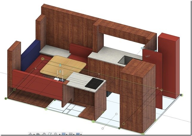 To help with your orientation, this screen shot from my Fusion 360 3D model shows where the Head & Shower are located in the front DS Driver Side of Lance’s Hab/Habitat/Box which is on the far Right of this view.
 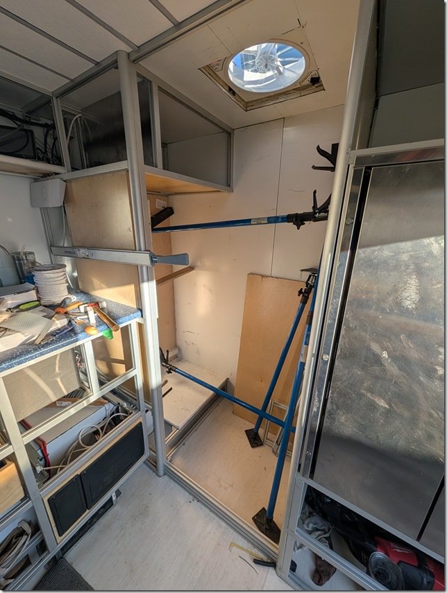 Here is what it looked like IRL (In Real Life) from the inside when I got started. That’s the SS Fridge/Freezer on the far Right, Blue DS Galley countertop peeking through on the Left and that’s the DS Front corner of the Hab in the far middle of this photo. The toilet will sit on top of the raised floor section and I’m getting ready to put in the the shower pan on the lower section of the floor that the blue cargo spreaders are resting on.
 I started prepping the interior by gluing 1/2” Baltic Birch plywood on the XAL eXtruded Aluminium framing of the two walls you see here on the Left and Rear. I use these adjustable Blue Cargo Spreaders (from Harbor Freight) all the time and here they are helping apply pressure to the freshly glued in BB plywood panels to keep them flat and straight.
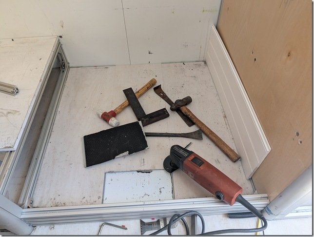 For maximum adhesion of the rigid foam Shower Pan I removed all the LVT vinyl floor planking that covers all the floor area inside Lance’s Happytat.
 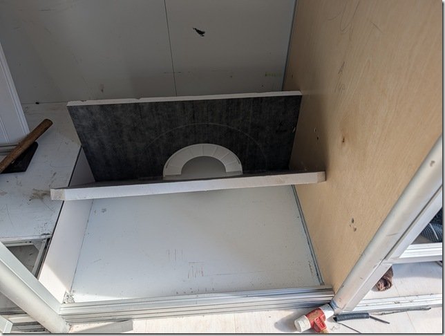 To help with tiling the shower pan and getting the slope to the center shower drain just right, I bought a Vevor shower pan kit that is specifically made for this purpose and adds even more insulation to the shower floor.
 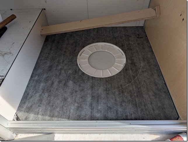 You can see here how the area for the flange of the PVC drain is already pre-cast into the foam and you’ll also note the large circular recess surrounding it for bedding the drain flange into the floor.
 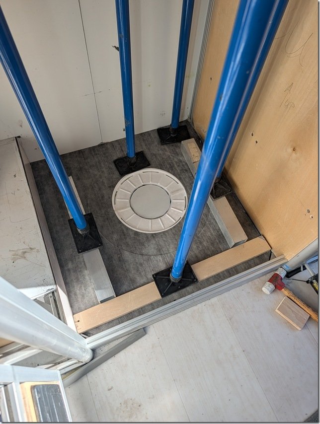 After checking that it all fit just right, I removed the foam pan, applied a silicone based adhesive with my cordless caulking gun (that I’m enjoying more ever time I use!), spread it out evenly with a notched trowel and pressed the floor pan back into place using my trusty cargo spreaders and some aluminium and plywood cauls to press it even and flat.
 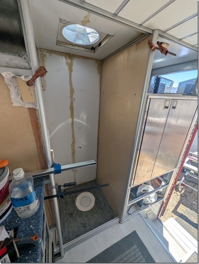 It was difficult to see in the photos above but I also used 1/2” BB plywood to cover the wall between the Shower and the Fridge/Freezer compartment. I caulked all seams and corners with construction adhesive for additional sealing of those.
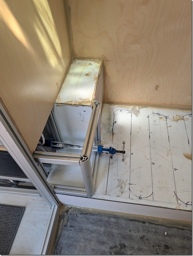 Next I put in this small bit of XAL framing to extend that exterior cabinet “bump” all the way to the inner edge of the Head raised floor. This will also create a handy storage area.
  Now it was time to completely waterproof every surface inside the Head & Shower to ensure that there are no leaks in the future. I used the ever popular RedGuard and brushed it on all the surfaces.
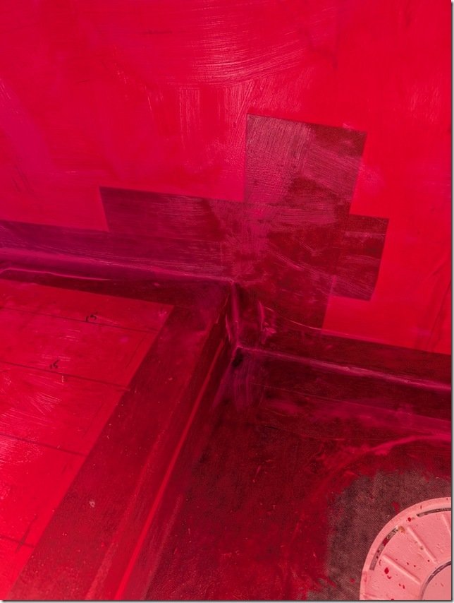 After the first thin coat of RedGuard was on I went around and used more RedGuard to bed in some reinforcing felt that I cut into strips and pressed into all the corners and seams with more RedGuard.
 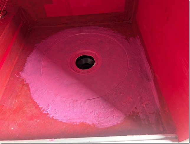 The drain area received several more coats of RedGuard as this will get the most traffic and potential for seepage. The pink colour is from the still wet RedGuard which quickly changes to Red as it dries fully.
 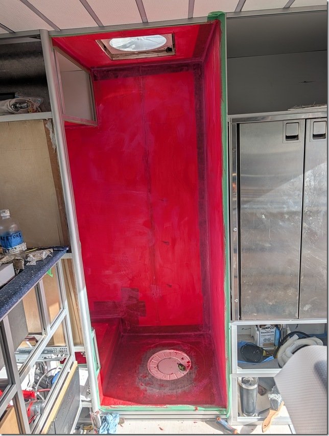 Et Voila!!
 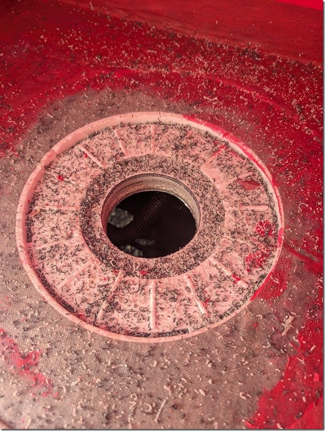 A bit messy but my 11cm/ 4 1/4” hole saw did a nice job of cutting this hole through all the layers of insulation and aluminium in the floor for the PVC drain to set into and exit out the bottom where it will connect to PVC pipe and on to the Gray Water tank. You can also see the 2 inches of insulation that are below the shower floor.
 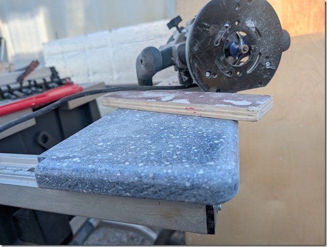 I had some of this Blue Solid Surface acrylic material left over from doing the Galley countertops so I used this to create a nicely contrasting and durable shelf top on that bump out in the Head.
 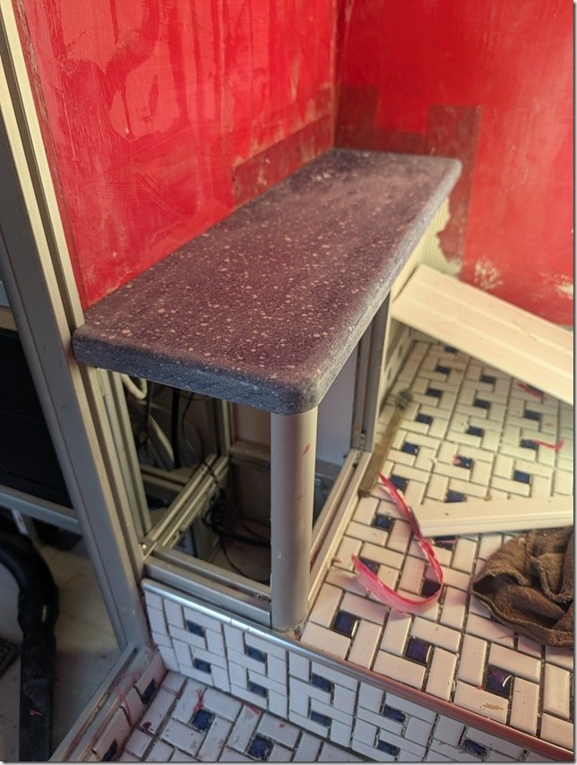 I wanted to get this shelf installed before I started putting in the PVC planking that I’m going to use to cover the walls.
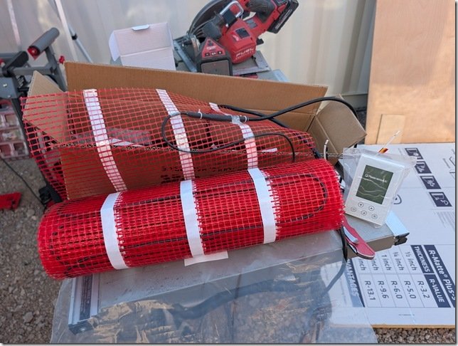 The kit comes with this Orange plastic mesh which the Black heating cable gets attached to.
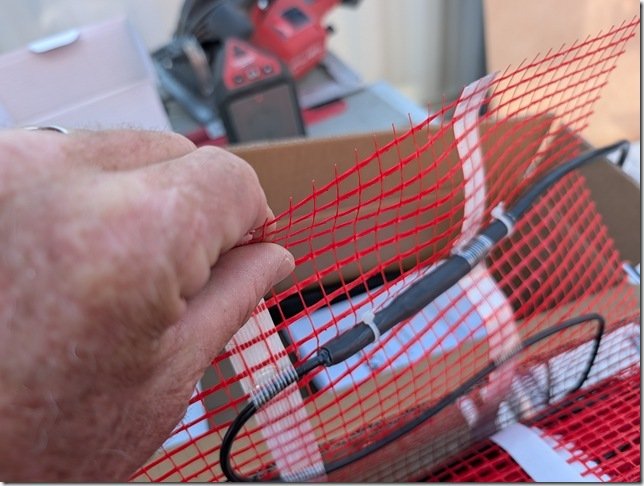 This is the transition piece where the cable changes from the 220VAC power cable to the heated wire. As it is a larger diameter I routed a groove into the ACM flooring so this thicker diameter would sit flush with the floor surface and be better protected.
 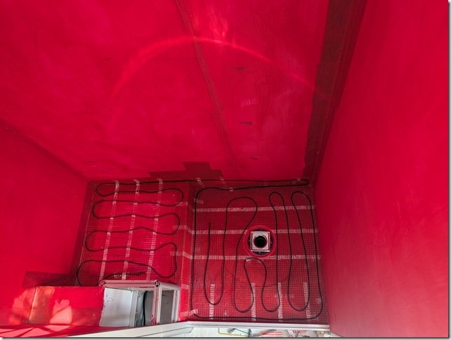 The heated cable is one continuous length and you can not cut this so it took me a bit of planning to get the spacing right but all fit in very nicely and will keep our tootsies warm both when showering and sitting on the Throne!
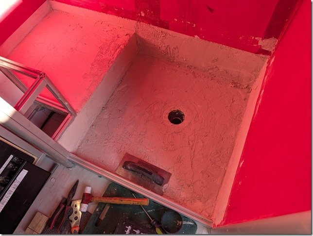 With all the heated cable and mesh in place I mixed up the epoxy thinsulate/mortar and spread out about a 13mm / 1/2” thick layer with a steel trowel and smoothed it all out.
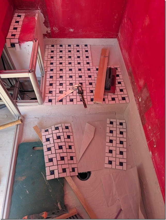 Laying out this type of spiral pattern is a bit tricky and takes some planning to make sure all the corners and joints line up and maintain the pattern. If you look closely you’ll see that you can only get a straight line for butting up against corners or lining up sheets in one place along the larger square formed by each spiral.
 Where I needed to cut some of the tiles such as around the drain, my trusty Dremel tool with a diamond cutting wheel worked like a charm to get nice straight cuts and smooth edges and you can maybe see along the bottom edge for this sheet I’m trimming square here.
  It had been a Looooooooong time, think decades, since I last did any tiling so I started with the floor in the Head as it will largely be covered by our Joolca “Gotta Go” separating toilet to cover any learning errors, but it all turned out quite well I thought.
 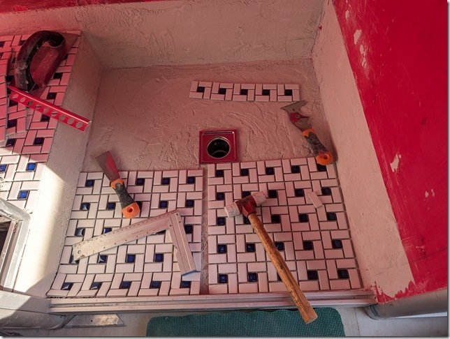 Then I moved onto the Shower floor and started the dry layup there.
 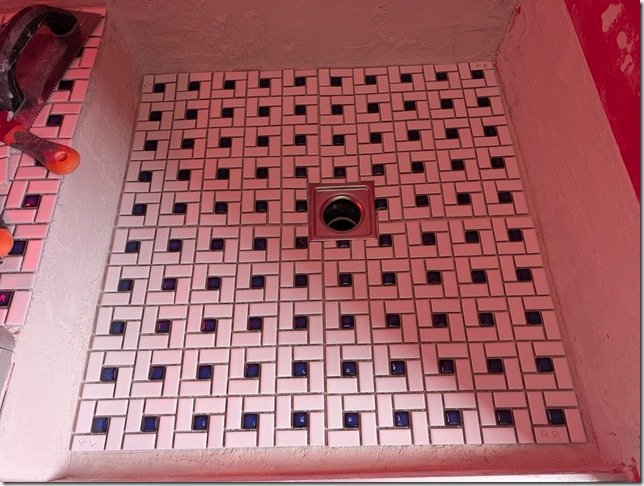 You can see how I needed to trim the tiles a bit along the edges of the square SS drain which I did so that the outer edges of the regular square spiral patterns would match up with the outer edges.
 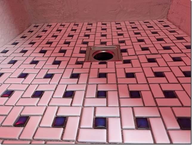 And it all slopes down from the edges to the drain.
 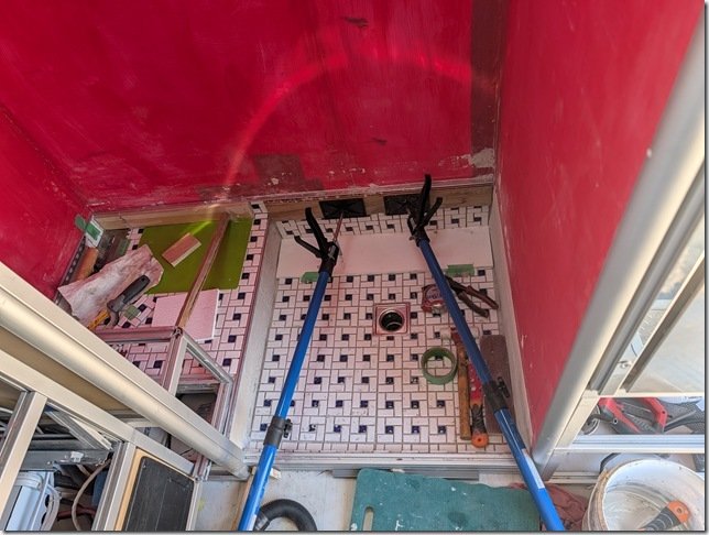 I thought it would look better to create a single upper edge surrounding the whole space so I put in some aluminium edging and tiled up to that along all the sides of the Shower and the Head floors and set them in place.
  For the walls I wanted to find the best combination of waterproof, easy to clean and good looking so I ended up going with these White tongue and groove PVC planks that are about 18cm / 7” wide with grooves molded in to look like narrower planks, and started cutting them to size.
 I picked up some aluminium edging meant to be used under tiles which you see propped up in the corner on the Right here and used that to make the transitions from tile to PVC planking. I taped off the top and bottom edges of the area for this band…………..
 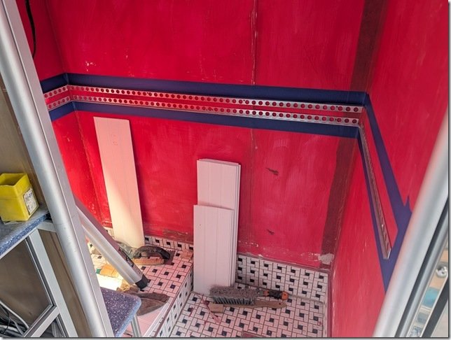 ………. and installed the AL transitions edging all round.
 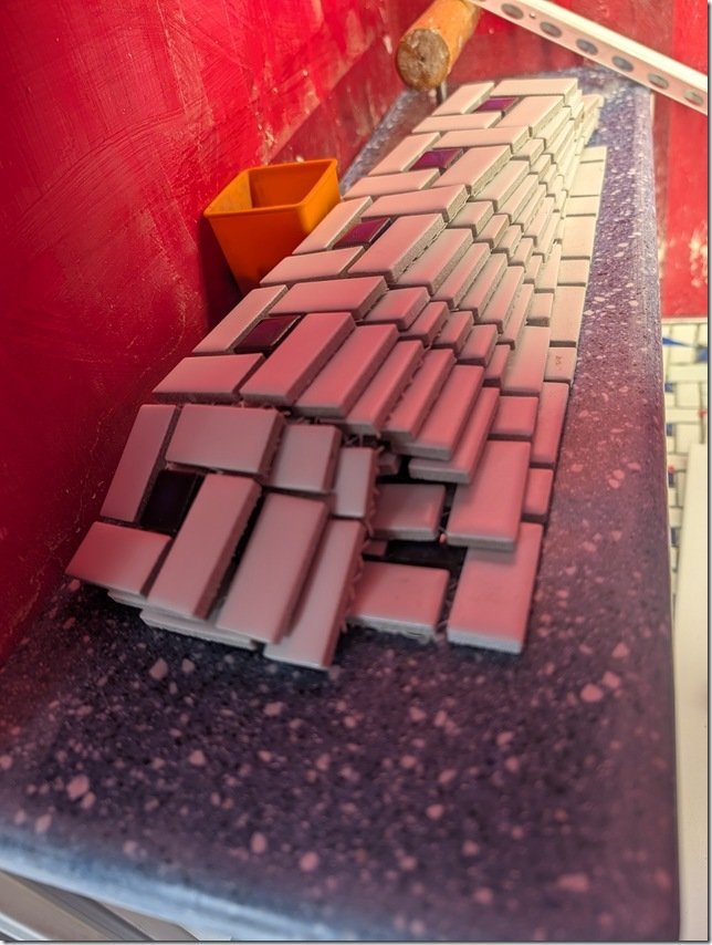 I had enough left over tile to cut these bands off the sheets and used that size to determine the width of the band.
 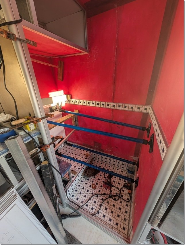 Worked out quite well and now time to put up all the PVC wall planks.
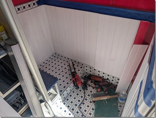 It was quite quick and easy to cut the 8ft long PVC planks to a nice fit between the top and bottom edges of the aluminium edging there the tiles start and stop.
 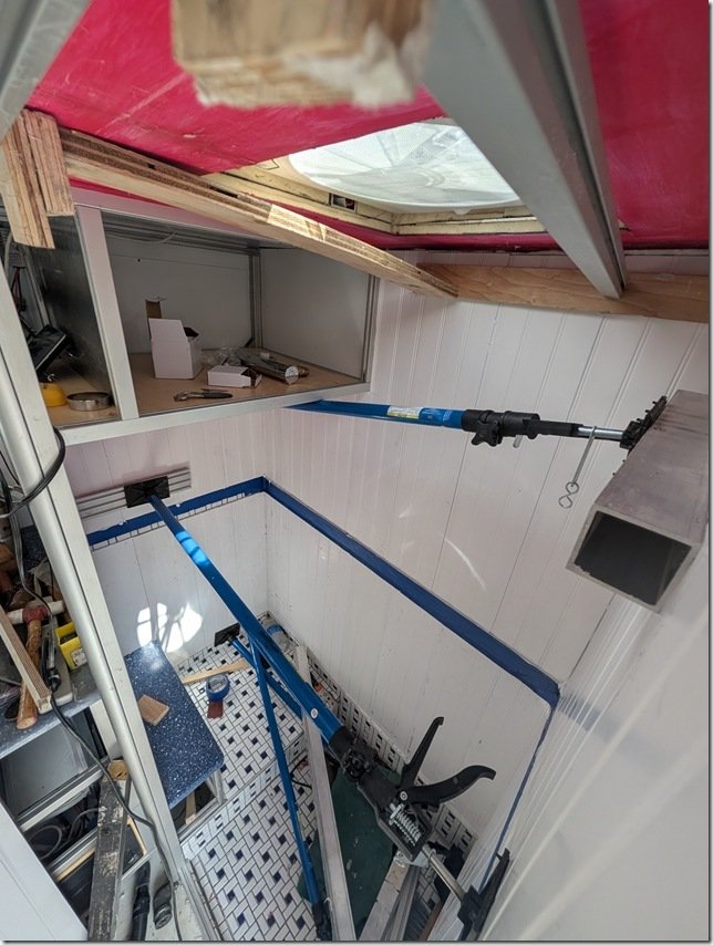 The cargo spreaders and some square aluminium tube cauls helped to hold the PVC planks flat while the silicone adhesive cured overnight.
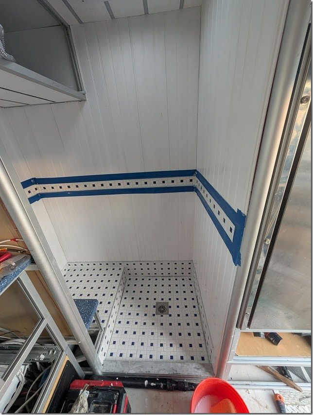 With the wall planks all done I could now grout all the tiles in this band and on the floors to finish the tiling.
 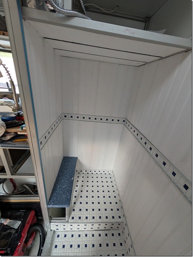 I did the ceiling with the same vinyl planking with a different pattern on it that I used for the ceilings in the rest of Lance. As with those other ceilings, I put in a strip of dimmable LED’s between each plank but more on that a bit later.
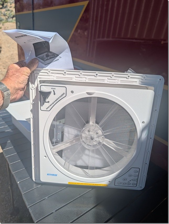 I’m not a big fan of the popular variations of the MaxFans that much of the RV and Van world seem to use and wanted to keep our overall vehicle height to a minimum and we’re at 2.9m / 9’ 5” right now with the solar panels and roof vent. So this Kohree vent unit seemed to check all our boxes.
 I had purposely left this space up on the roof in front of the four 450Watt solar panels and their Super Strut rails so now time to cut the only hole in our otherwise seamless one piece roof.
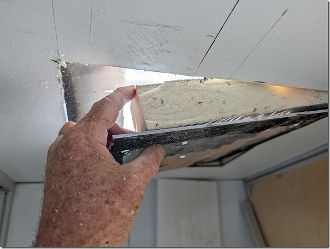 There are three thick aluminium plates in the roof of Lance, one for the top skin, the layer you can see here that forms the internal ceiling of the ambo box and then ……
 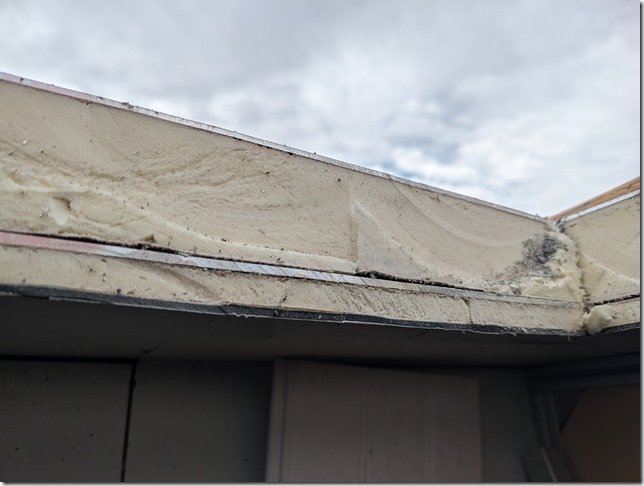 ……… the final layer of 5mm thick ACM that I installed for the ceiling surface below the additional layer of 20mm IPS foam insulation.
 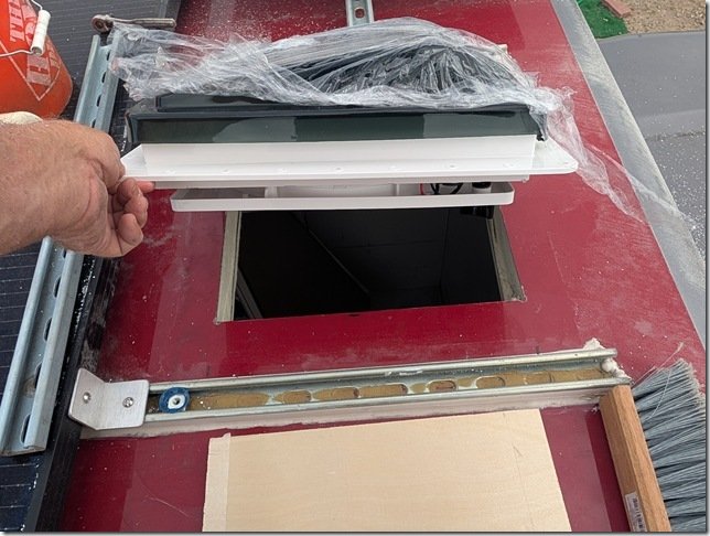 The vent dropped in just right.
 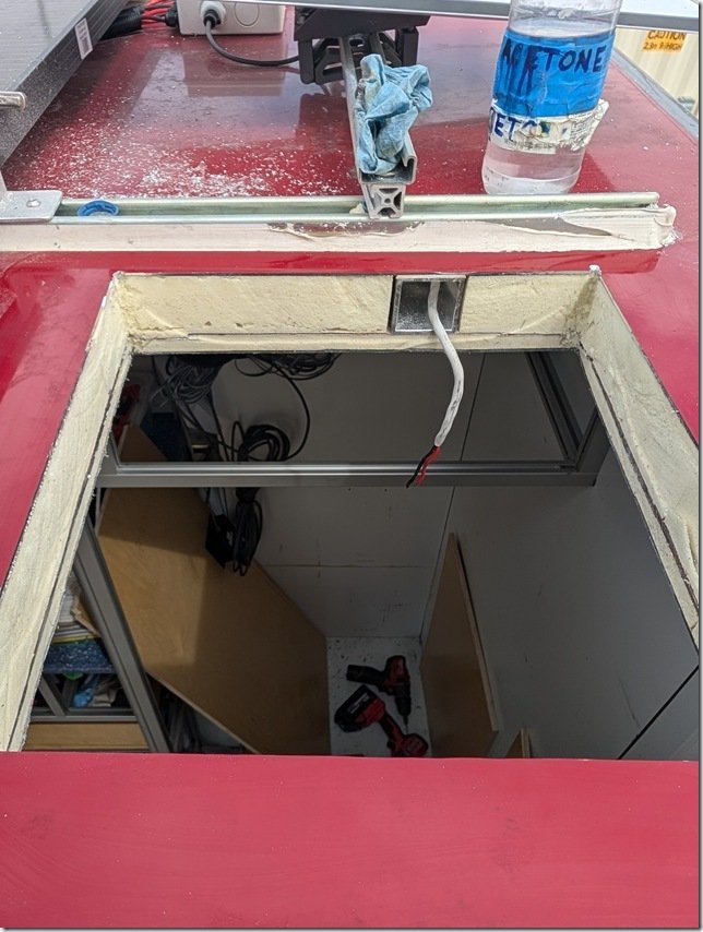 I used this 2×2” square AL ceiling beam for a conduit for the wires to power and control the fan.
 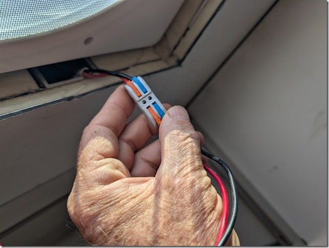 I’m a BIG fan of these WAGO wire connectors and have used them throughout the build. They worked well to connect these 12VDC power wires to the fan and then tuck nicely into that square AL tube.
  Checked everything for a good fit including this trim frame and then ….
 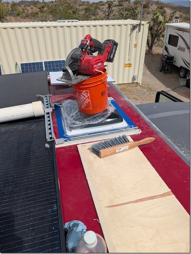 ………. bedded the vent into the roof with 3M 5200 sealant and some makeshift weights to let it cure overnight.
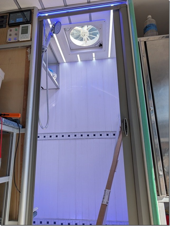 Worked out well to provide Goldilocks just right lighting both night and day.
 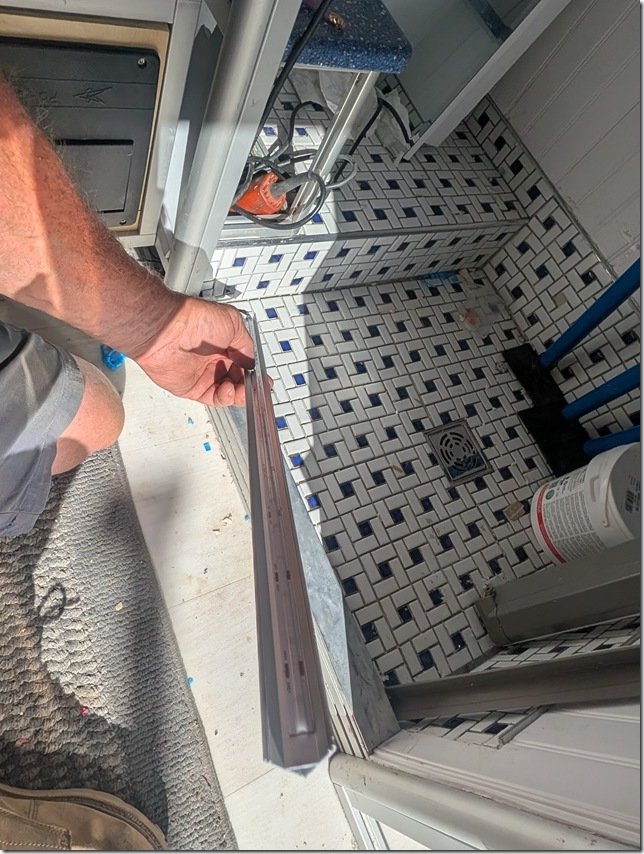 One last detail for those few times (so far) either of us needs to get up and use the Head in the middle of the night, I wanted also have some indirect low level lighting inside the Head & Shower area. So I installed some of these 45 degree angled aluminium extrusions in hidden areas such as under the door sill into the Shower you can make out below my hand and another under that little Blue shelf in the Head.
 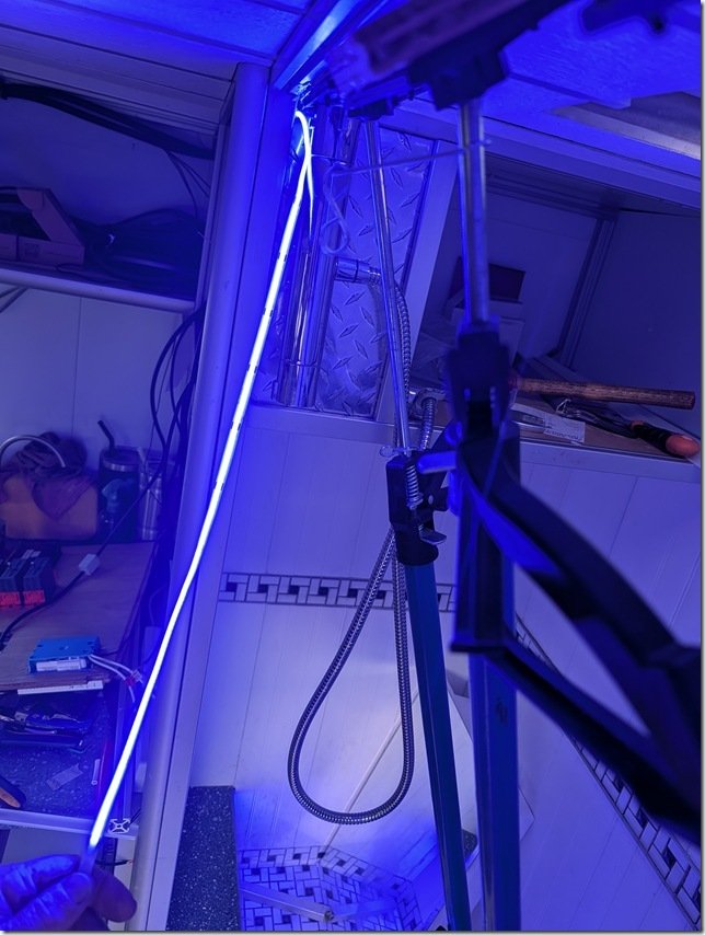 To help keep our night vision and add a bit of “ambiance” I used these Blue LED strips which are also dimmable to whatever level of Blue light you’d like.
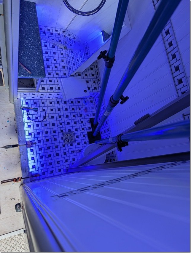 Testing out the LED strip tucked in below the door sill into the Shower.
 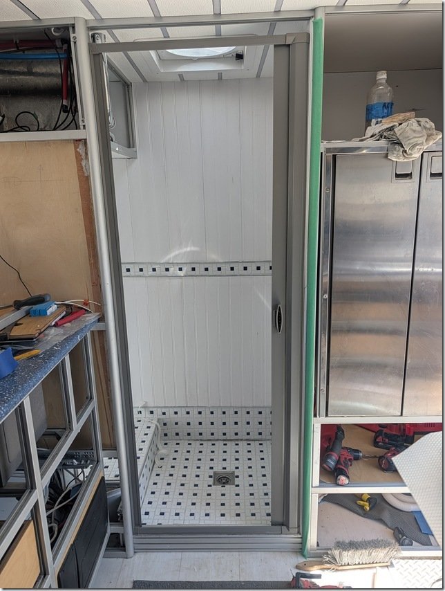 After some debate and research we decided to go with this retractable shower door that rolls up when OPEN like this
 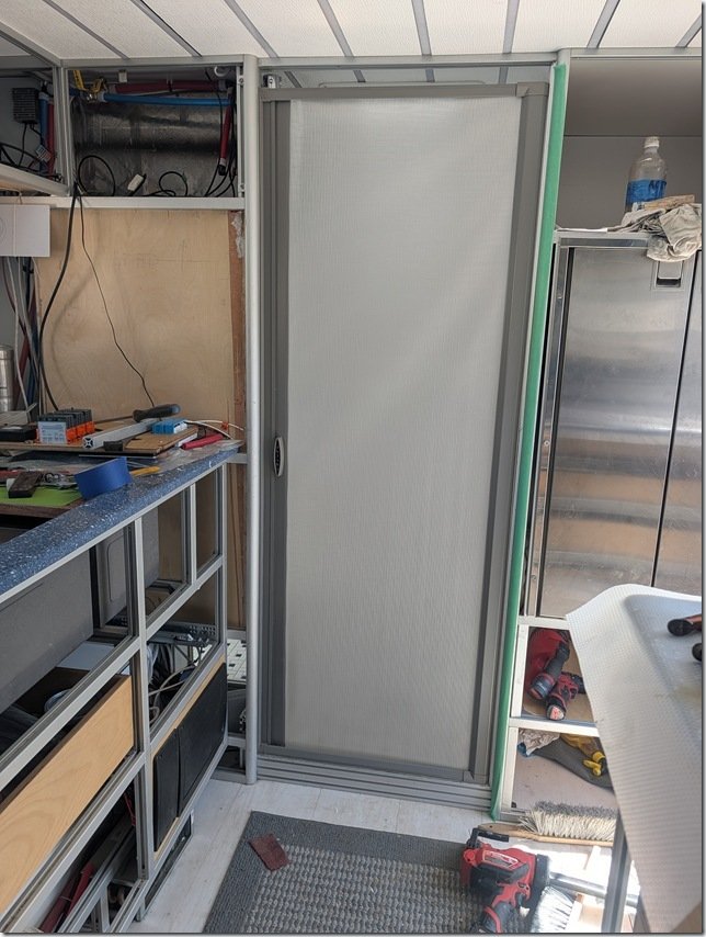 ….. and then rolls out to seal and CLOSE like this.
 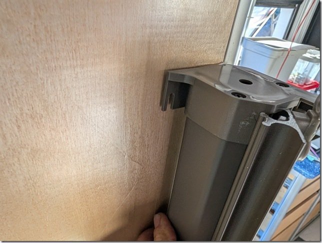 The flexible material rolls up on a spring loaded shaft hidden neatly inside this cassette that mounts to the left side of the door.
 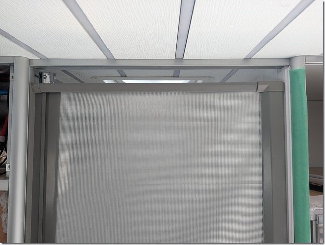 The “door” slides on tracks concealed inside the AL extrusions top and bottom and I left a small gap at the top to help with air circulation.
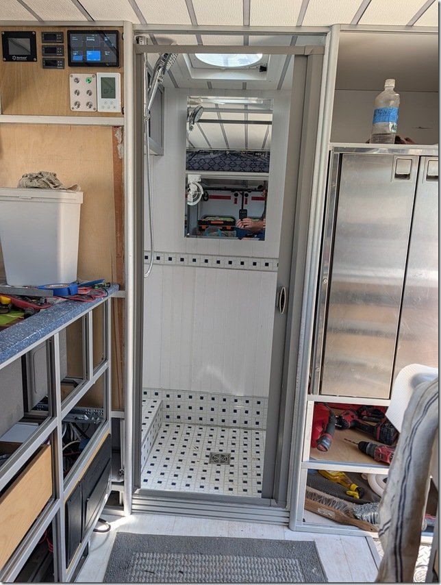 And then mounted this mirrored Medicine Cabinet on the rear wall to finish things off.
  an’t have much of a shower with no water so along the way I installed this very nice adjustable hand held shower head that has a full shut off valve on the handle and ….
 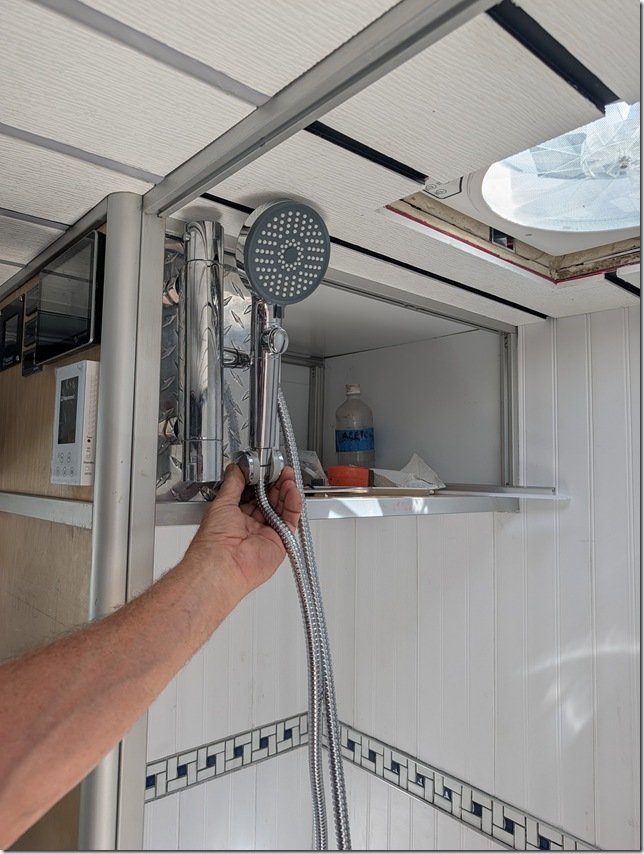 …… connected it to a thermostatic controlled mixing valve faucet. These are great for maintaining a whatever water temperature you set it to coming out of the shower head. The button allows you to turn the water on and off as you wish to conserve water and have it off when you want to wash your hair, shave, etc.
 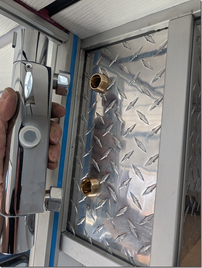 The SS cylindrical knob on the top end rotates to set the temperature and the one on the bottom controls the water flow volume.
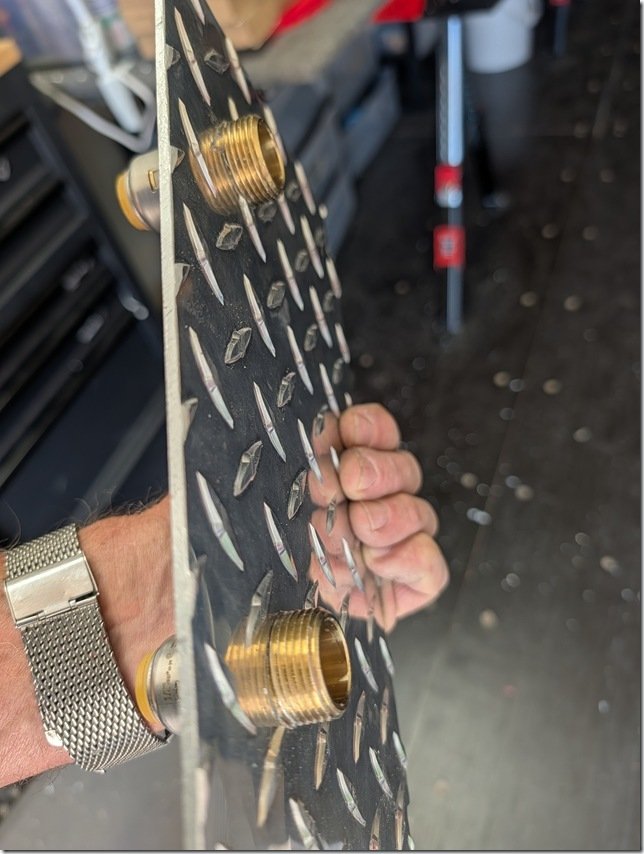 I drilled and threaded this plate to mount these two brass fittings for the thermostatic valve to attach to on the outside and push-connect fittings on the other side …………
  …… for the Hot & Cold water 1/2” PEX-A lines to attach to.
  The Yellow handles are shut off ball valves on each PEX water line for servicing or winterizing.
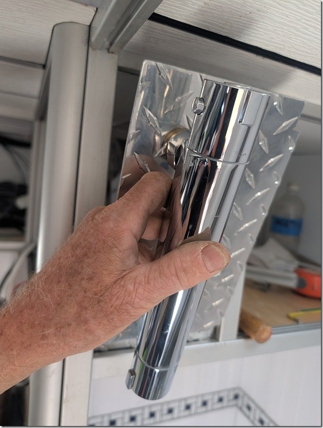 The whole assembly then fits securely into the slots in the XAL framing.
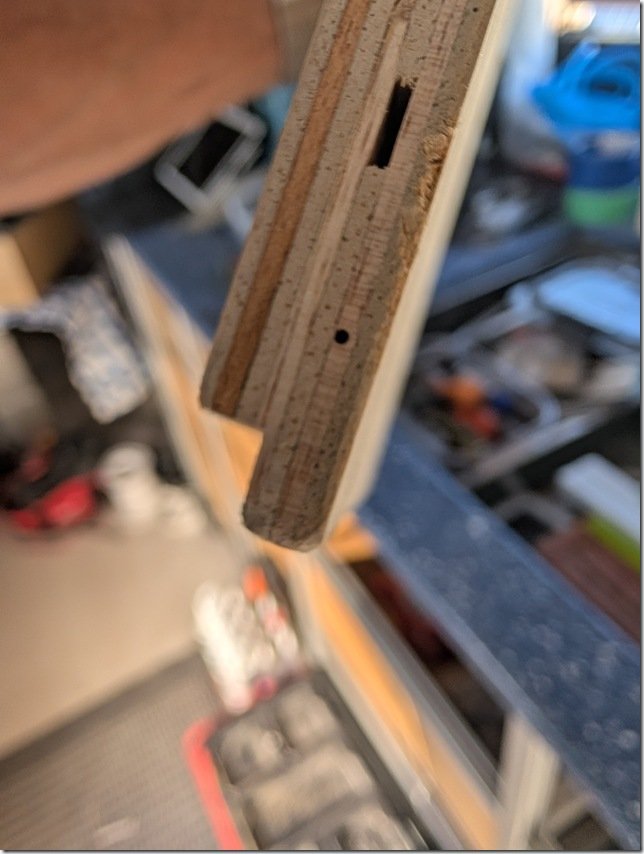 I cut this rabbet or tongue on the bottom edge that is a snug fit into the groove on the bottom length of XAL framing.
 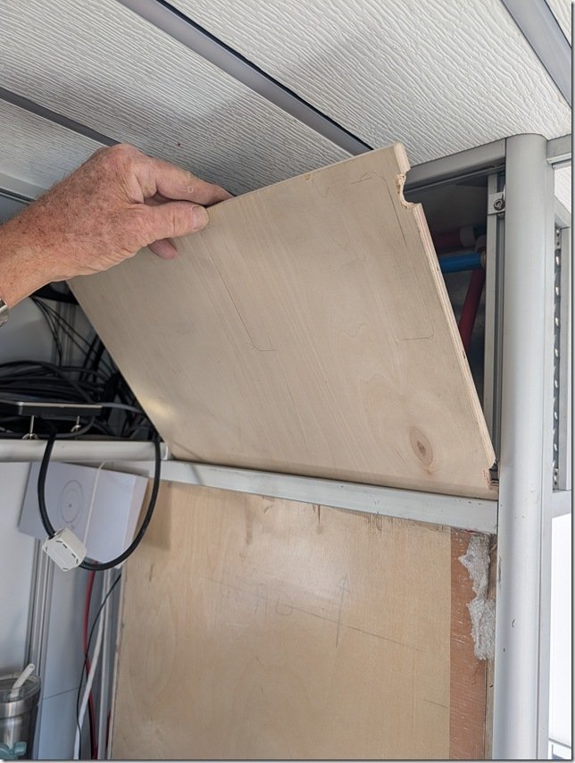 The way it works is that you first put the bottom tongue into the groove and then ……..
 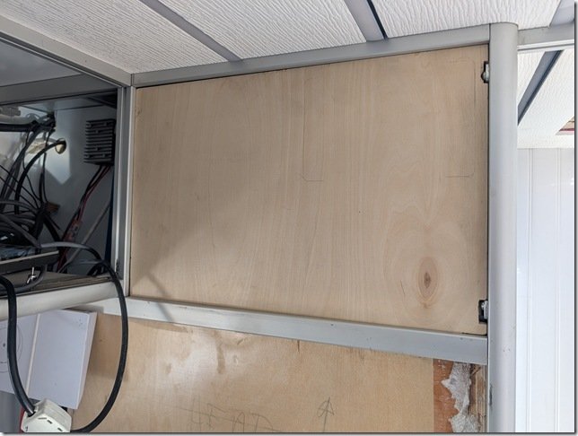 …………… tip the panel up into place.
 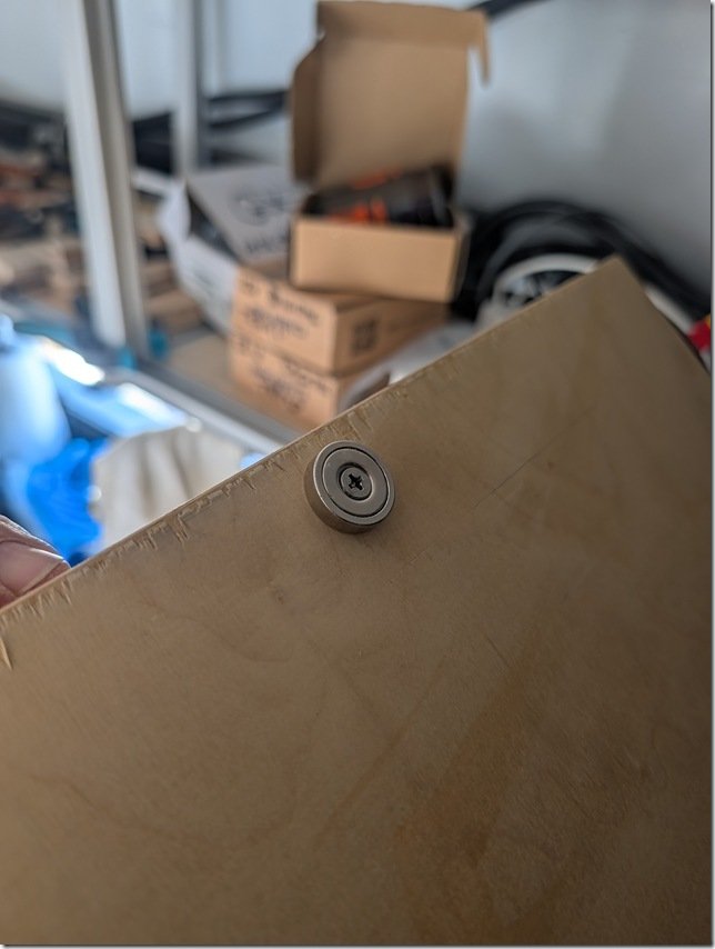 To hold this and likely all the panels in Lance securely in place, I’m trying out using these very strong round “donut” Neodymium magnets. This one is a 40 pounder, meaning it takes about 40 pounds of pull to remove. These magnets are available from less than one pound up to over one hundred.
 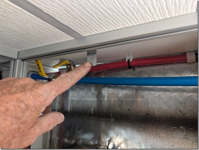 All the metal in Lance is aluminium which of course isn’t magnetic so cut a short 5cm/2” length of steel flat bar and drilled a 6mm hole in one end so I can bolt it to a T nut captured in the XAL slot on the back here. Worked out even better than I hoped and the panel snaps into place with a good “thud” and locks the whole panel tightly in place.
 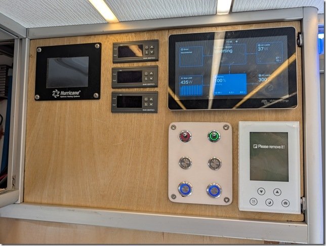 Here is what the panel looks like so far. White thermostat for the heated floors in the Head & Shower in the bottom right (currently turned off) and the Victron Cerbo GX touch display above it and switches for things like water pump, Starlink power and the thermostatic controllers for the heated main cabin floors over to the Left.
 Easily one of the most used and most important areas for our day to day live in Lance and our 10,000 + mile “maiden voyage” this past summer proved that our design worked well as we used it during that two month test drive. We prioritized large areas of open countertop, dual deep sink, induction cooktop and large fridge and freezer and you can see the basic layout from the 3D model screengrab here.


 Underneath both countertops it is all drawers as we find these much more efficient to use than cupboards and overall we have more than 20 drawers inside of Lance.
  I have always preferred dovetail joints for all drawers given their superior strength that stands up for decades of use and I think they look great too and so that’s what we went with for Lance. I was going to do this all myself but with almost a hundred dovetailed corners to do and SO many other jobs demanding my time and attention I decided to job this out. I found a fabulous company to work with called
  They shipped all the pre-cut drawers to me as flatpacks like this so the whole shipment of all the drawers was not too large and they were all very well shrink wrapped and carefully boxed up so they arrived with no damage at all.
  They also offered a great prices on the the top quality Blum undermount ball bearing drawer slides I wanted so it all came as a single order which made my life easier.
 Mounting more than 40 drawer slides to the XAL framework was very straightforward but time consuming to get them all exactly parallel and lined up.
  and some required a bit of Houdini moves to hold in place and tighten up.
  Next, I set up a little workbench on top of the PS Galley counter to assemble each drawer.
  Each set of dovetails only required a few drops of wood glue and they went together very well with two bar clamps and some taps with my little hammer to get the joints to fit together all the way. The dovetails were so precise that every drawer went together perfectly square and were solid as a rock.
  The Blum drawer slides required two slots in the bottom of each rear drawer side so I cut those out next and then I mounted to the Orange locking hardware to the bottom of the front corners. These are where the drawer slides clip into the drawer and make it very easy to lift out a drawer at any time. It’s a great system!
  Installing each drawer was now a simple process of pulling out each drawer slide……….
  ………… setting the pins in the rear of each drawer slide into the corresponding holes I had previously drilled and pushing them closed till they clicked in place.
  Et Voila! We’ve got drawers! Sad to say that I wasn’t able to get this done before we left on our big summer adventure so we REALLY appreciate having these now!
  I wanted all surfaces of these drawers to have a tough durable finish and decided to go with this two part Rubi Monocoat finish that you put on by hand with cloths rather than brush or spray. Hand rubbed finishes have always been my favorite and while this was a new one for me I was eXtremely pleased with the end result and the whole process of applying it.
  It was a bit laborious and a good workout but a very satisfying process for me.
  Difficult to see in photos but the Baltic Birch plywood came out with a glowing warm colour and a very tough finish that is also very easy to reapply in the future.
  To reduce the loss of usable space under the sinks I used these low profile P-traps which have turned out to work very well.
  and only required a small cut out on the rear of the two under sink drawers to clear nicely.
 For lighting, I decided to use COB (Circuit on Board) LED strip lights which I set inside lengths of 20mm wide black aluminium U channel which I ran in between each of the White PVC ceiling planks. I like these newer COB strips for two reasons; they provide an uninterrupted line of light rather than individual points of light in the regular LED strips and they can be adjusted from about 2200K (very warm amber) up to 6500K (daylight white).
  Once I had the layout done and the strips of PVC and AL channel cut to length, the process went quite quickly. I could apply the construction adhesive to each plank and AL channel and press them up into place and then use my super handy cargo jacks and some scrap lengths of XAL to press these all up against the ceiling so they ended up flat and aligned.
  You can buy the COB LED lights in 20 meter rolls which you then cut to the lengths you want and solder three wires to the copper strips underlying the Yellow COB light strips. Takes a bit of practice to get these tight solder joints without any cross connections but all went pretty well after a few practice solders.
  Then I twist the wires to help reduce any electrical interference and slide a clear tube of heat shrink tubing over the joints and shrink them in place for a nice clean and protected connection.
 ……………. I could now press these clear covers in place.
  Here’s the result at about 6000k. These LED light strips are also fully dimmable so you can adjust both the colour temp from warm to cold white and from off to full almost daylight brightness.


 Living the nomadic and remote life that we always have, we are big fans having solar power be the primary source for all our daily electrical needs, which are quite extensive. On our boat Mobius we had factored solar panels into the design from the beginning and were able to have 16 large panels on three different roof surfaces on that boat such as these eight panels on the upper Pilot House roof.
  And here on Road Runner Ranch we have 18 solar panels in two banks, this one just set against one of our 40 foot shipping containers and the others you can see Razz laying on above. These keep our big EG4 Wall Mount 15kW battery charged up every day and running this through our EG4 6000XP Inverter/Charger provides all our electrical power for day to day life here.
  This is where the time I spent meticulously building Lance in a 3D model using Fusion 360 pays off. I could create a model for each of the different solar panels that I was considering and see how they would fit onto Lance’s roof and on the framing.
 After much deliberation and testing in the model, I decided to go with four SilFab 420 Watt QD panels which I purchased from Current Connected almost a year ago now. I was able to get these all installed this past May in time to help power us on our marathon maiden voyage with Lance driving out to Portland Maine and back this summer. For those interested you can see all the specs of these panels here and of course with the march of time since there would now be even higher output panels but we’ve still ended up with 1680 Watts of solar power and it has been more then enough to keep us fully powered all the time.
 I
I I added additional 4 foot lengths of Super Strut so that I would have a mounting system for the whole 14 foot length of Lance’s roof for mounting any additional items in the future.
  I kept the mounting very simple as well by cutting pieces off a length of 2” aluminium L bar,
  drilling two holes in each one for the mounting bolts,
  and using the very handy Super Strut M8 threaded inserts to bolt them solidly to the lengths of Super Strut.
  Quick, strong, simple; what’s not to like?!!
  I then made up the cables using extra UV rated cables, Red for the positive and Black for negative and crimping the MC4 twist lock connectors that are the most commonly used for solar panel wiring and which I’ve used a lot in previous projects so I have all the specialty tools, crimpers, etc. some of which you see here in the photo.
  To fasten the brackets to the solar panel frames themselves I inserted aluminium M6 threaded Riv-Nuts into holes I drilled into the vertical AL frame on the solar panel and then used this tool which compresses the threaded inserts and locks them to the frame.
  End result looks like this.
 For those wondering, I fastened the lengths of Super Strut to the roof using Loctite 8X PL Premium Fast Grab which is supposed to be 8 times stronger than traditional construction adhesives which I’ve used before. Probably overkill but you certainly don’t want solar panels flying off the roof when running down the highway at 70 miles an hour! To prevent any pooling of rainwater between the surfaces of the roof and the Super Strut I caulked all the edges with 3M marine sealant which I have LOTS of experience with on our previous boats. So everything fully sealed and eXtremely well fastened to the roof.
  Solar panel output drops off significantly with the rise in temperature of the panels, the irony of which isn’t lost on me, so I left this 4” gap where the two panels down each side meet up. This along with the 2+ inch space between the panels and the roof keeps them as well ventilated as possible and the efficiency of their output was very good even in the 40C/105F days we had several times on the trip AND while I was installing these panels! Talk about a cat on a hot tin roof! Ouch!
  To make it a bit easier to run the cables AND give me a wee bit of shade, I was able to remove the inner brackets and use the outer ones like a hinge and prop up one lengthwise pair of panels while I ran the cables.
  I ran the eight cables for all four solar panels to converge at this point on the front DS corner as this puts it directly overtop of the Electrical Cabinet below where they need to go and thus provides the shortest cable run for least voltage drop. I drilled the only hole in the roof for this but it was a BIG one as you can see and then I used more 3M 5200 to seal a short length of 2” PVC pipe as a safe conduit through the roof for these and all other cables in the future. The red square you see on the bottom is 3M VHB Very High Bond two sided tape which is a fabulous product for gluing almost anything to anything and it never comes off.
  PVC
PVC Each
Each This is what it looked like inside the Electrical Compartment where the cables pass through.
  The output of solar panels is a much higher voltage than the batteries and needs to be regulated to different charging stages to properly charge the big LiFePO4 Lithium EG4 batteries in Lance so the output of the solar panels goes through a MPPT controller which looks after all of this. Although it isn’t common, the most efficient setup is to have a dedicated MPPT controller for each panel and so that’s how I’ve always built our solar systems. Those are the four Victron Blue boxes you see on the upper Right here.
  It’s a bit of electrical spaghetti and took a bit of time to route and connect all these cables but keeps all the wiring very well contained in the wire ducts like the one running vertically up the far Right side and will have a cap that snaps onto those fingers you see here.
  Final
Final
 The extra length of Super Strut has already come in handy for my temporary for now mounting of our Starlink dish and the 4” PVC tube running down the middle for storing long lengths of material I like to have for ongoing projects while we’re on the road. Go ahead and tell me you’re surprised?!?!
 and “Sunny Boy” as he tells me he now likes to be called.


 For those interested in the details, this is the make and model Mini-Split we decided on. It is a 9k BTU capacity “Pioneer Diamante Ultra” that is one of the most efficient models they make rated at 23.5 SEER for those who know that system. These type of two part aircon/heating systems are referred to as Mini-Splits because they consist of two parts; the outside condenser/compressor and the inside air handler evaporator.

 Back to the Mini-Split install, this is the wall mounted interior evaporator half of the system and I mounted this Air Handler above the entry door on the front passenger side of the Hab. Works out well as you can see being almost the same width as the door. There are moving louvers with one large one running across the bottom that you can see partially open here that distributes the cold/hot air up/down vertically and then inside are a set of other smaller louvers that move back and forth sideways and help move the air left and right. So this location works out very well for the heating/cooling of the interior air and yet keeps it from blowing directly on us when we are at the Settee or in bed.
  As you might have noticed in the earlier photos, I had to cut away part of the upper stair in the entry to fit this top right corner of the exterior half or condenser/compressor. Once I had this all solidly bolted in place to the frame of the Hab underneath (see that May post for details if you’re curious) I finished it off by building a little “cage” using extruded aluminium and some aluminium diamond plate that I had left over from cutting out some of the original ambulance cabinetry. Also added some insulation to keep the other heat/cold from getting into the Hab.
  The 6mm diamond plate slid nicely into the T-slot grooves of the extruded Aluminium or XAL as you can see here.
  All these interlocked plates and XAL turned this into somewhat of an Origami project as I needed to be able to slide some of those plates out to get inside to connect the wiring and refrigerant lines but I was quite pleased with the way it turned out in the end and still functioned well as our entry stairs.
  I chose the 240V model as it is a wee bit more efficient than the 120V versions and I designed our AC system that I’ll cover in more detail in a future post, to be a Split Phase system so it provides both 120 and 240 Volt power.
 Looking inside the entry door, the drawers on both sides of the Galley are 24” deep but the countertops are 32” so there is a nice space behind the drawers when they are closed.
  This is the space behind the bottom drawer on the Left side of the stairs as you enter and I drilled a 2” hole through the vinyl flooring, insulation and aluminium floor of the box. The Pioneer unit came with the white PVC insert to protect the copper line set and the white cable is the 240VAC power and the black is the communication cable between the two halves of the Mini-Split.
  Up above I drilled two overlapping holes in the solid Acrylic countertop, which is fabulous stuff to work with BTW, and ran the electric cables and copper line sets through this. The copper lines in the interior evaporator unit come permanently fitted and they ended up just above the countertop height so I cut the new copper lines and installed new flare nuts that allowed me to connect them here and then run down into the compressor/condenser unit under the floor.
  The upper parts of the line sets gets covered with this black EPDM insulation and the corrugated clear hose is where the condensation produced by the evaporator drains out and down through the floor onto the road below.
  To protect and hide all these lines and cords I built a small vertical connector between the countertop and the overhead cabinet you can just see at the very top of this photo. The sides will soon be fitted with Cherry panels same as all the fronts of the doors and drawers that will be the topic of several other future posts.
  I
I Most importantly, Razz and Zoe use this new little upper step for their water bowl and so they give this new addition two paws up!

 and this is the overhead cabinet above the DS Galley countertop.
 You can see a bit of the detail of the way I am connecting all the various lengths of XAL which are all 1 inch square with either 2, 3 or 4 T slots.
  You can also see some additional XAL framing above the Entry Door into Lance’s “Happy tat” which I’ll explain a bit more in a few minutes.
  Peering into the Fusion 360 3D model of the Happytat might help to give you some perspective of the overall layout. L-shaped Settee in the Rear (far left) with the Queen Bed (not shown) raised up into the ceiling and the two Galley countertops on the PS and DS in the middle and then the Fridge/Freezer PS front with the shower in between that and the Head/Bathroom on the DS front (upper Right here)
  The last bit of XAL framing when pretty quick and easy to put the last piece of the L-shaped Settee into place for the seat that goes across the back in front of the two rear doors of the Happytat “box”.
  Not to get too far ahead of ourselves but thankfully my Beautiful Bride has been taking some time away from her writing to create these drawings for the Settee cushions with the help from some AI of course to create these sketches a bit faster. She is now working with a local upholstery guy up in Vegas as we simply don’t have the time to sew these ourselves.
  This is a sample swatch of the upholstery fabric that Christine has found and we both really love.
  ….. and this is the beautiful (we think) glass and stone tile that she found and should be here in a few days.
 We found this Blue Lagoon pure acrylic at Solid Surface.com (where else?!?) and got a great price at $639 for this 1/2 inch thick 144 inch x 30 inch slab. They did a great job of packaging it all up and it arrived in perfect condition.
  Would have been a bit of a challenge to bring this 12 foot slab the 75 miles back to RoadRunner Ranch but I needed two pieces that were just under 6ft each so I brought my handy cordless circular saw with me and cut it in half and loaded it into Totu our 2006 Toyota Tundra, and we were off.
  Well, I did make a quick stop while I was up in Henderson (south part of Vegas) at our favorite Home Depot to pick up four sheets of 1/4” and 1/2 thick Baltic Birch plywood and these two other boxes which you’ll just have to wait for a bit to discover what’s inside them.
  This 1/2” solid acrylic material was very nice to work with using my regular carbide tipped saw blades and router bits and after some careful “measure twice, cut once” checks between the model and the actual interior I quick had the larger DS Galley countertop cut out.
  With the cutouts to go around the intersecting XAL parts and the bed lift linear actuators on the far Left here, it was a nice close fit.
 We like the look of thicker exposed edges around all the countertops so my next step was to cut 1” and 2” strips of the acrylic sheet and glue them along all the edges and overtop of where the countertop attaches to all of the XAL framing underneath. Pretty simple process using a purpose made epoxy glue and matching gun you can see in the middle Right and then clamping the two mating surfaces together.
  Now for the FUN part! Cleaning up all the now 1” thick edges where the two pieces had been glued together. The clamp on strait edge was a bit help to quickly have a straight guiding surface for me to hold the base of the router to and shave off the edges.


 …….. and then switched to a 1/4” radius bit for the bottom edge as we thought this combination looked and felt the best.
 …… provided Christine with some chuckles and entertainment courtesy of her very own Frosty the Snowman.
  Now on to the details starting with the cutout for the nice big and deep SS sink.
  Once I had the large opening cut out with the circular saw I cleaned up the inside edges same as I did with the outer edges using the router and a 1/2” radius round over bit to provide what we thought was the best look and feel for the undermount sink.
  Gee, actually starting to see a Galley in here!
  With the sink test fitted and approved, next detail was to use this flush bottom router bit to cut a shallow recess in the XAL where the edges of the SS sink would sit down flush with the rest of the XAL surfaces.
  This was necessary so that the countertop would sit perfectly flush on top of all the XAL and sink edges.
  The final result was well worth the eXtra effort to get this clean fit between the undermount sink and the countertop material.
  One more job checked off the list!
  Moving over to the PS Galley, next job was to fit this lovely 2 burner induction cooktop into the countertop using the same process as the sink……
  ………. layout the opening with masking tape and pen, cut out the opening with the circular saw and Japanese flush cut hand saw…….
  ….. a little bit of filing to put in some small grooves for the screws in the side edges of the cooktop and it slid into place just right.
 If you peer through the mess you just might be able to see quite a large and lovely two sided Galley?!
  Final bit of kit to finish off the Galley for now was to install this marvelous dual kitchen faucet that we can’t wait to try out.
  Quick and simple install, just drill the 1 1/4” hole in the countertop, assemble the braided SS Hot & Cold hoses into the base of the faucet and insert through the hole. A brass nut then slides up from below and threads onto the base of the faucet with washers sealing both sides and it is ready to be connected to the hot and cold PEX hoses when they go in on the upcoming plumbing phase of Lance’s transformation.
  All the potable water we put into the two 170L/45 USG water tanks will go through a set of three filters but to clean it up to the next level I installed this Acuva UV water filter with its own faucet.
 Then make the 2 mile drive into the booming metropolis of Searchlight (pop 245) to this “secret” water tap carefully tucked away on this abandoned lot courtesy of one of our neighbors “Amber”. This is fresh out of the ground from the large wellhead that provides all the “city water” to the homes of residents of Searchlight and has incredible pressure and volume so only takes me less than 20 minutes to completely fill the IBC Tote.
  Then drive back home to RoadRunner Ranch, connect the hose to the large valve on the bottom of the IBC Tote which leads into …….
  …… here and use an electric pump to transfer the water into our four IBC Totes stacked up inside the end of one of our two 40ft shipping containers.
 Yup! This awemazing 9000 BTU Pioneer mini split ductless inverter heat pump.
 I’ve been quite blown away by how much these units have increased their efficiency in cooling/heating/dehumidifying and even more so with their power efficiency.
 Do you recall me pointing out the additional XAL framing I installed above the Entry Door into Lance’s Happytat? Well here is what that was for. I put in two vertical XAL supports in the framing above the door and so all I needed to do was bolt in the mounting plate that Pioneer includes with all their Mini-Splits and then you simply lower the unit onto this plate and click it in place!
  One of the benefits of doing a custom build is that you get to make everything a Goldilocks (just right) fit and this is a good example.
 Looks may be a bit deceiving here in terms of the headroom when going up/down the entry way stairs but we had calculated this all out and even our taller friends well over 6ft won’t have to duck or have any limitations getting in or out.

 Whatta ya think?Is it going to fit?
  Well I did say this was going to be a shoe horn fit, and for a change this was NOT hyperbole as you can see!
  With a little help from my friends; Misters Crowbar, floor jack and ………..
  ……… tie down ratchet strap, guess what?
  Once I knew for sure it would actually fit, however closely, my next challenge was how to hold this 24kg/52lb unit solidly in place?
  Here is how it was looking underneath around this time.
  See that spot at the rear between the Pioneer unit and that black leaf spring holder on the frame of the Kenworth chassis?
 In
In Added 2” of PolyIso rigid foam insulation for acoustic and thermal isolation and then started to fabricate rectangles of AL diamond plate that slid just perfectly into the slots in the XAL framing.
  This simple little new step turned out to be quite the challenge of its own as I always consider future access for maintenance and repair into my designs and knew what I’d need to be able to access the forward side of the Pioneer unit for connecting the electrical cables and copper lines for this initial install and any future work that might be required.
  I used to love making little wooden puzzle boxes that had a specific pattern of sliding intricate pieces to open it up and this experience came in eXtremely handy here as this step box turned into an origami puzzle of its own. That side facing plate you see above slides down, then the top frame and its encapsulated plate slide out ………
  …….. and now you can slide the front facing plate up and out……..
  …. to reach the end goal of accessing the electrical panel.
  I fabricated this new cover plate and glued the wiring diagram from the original cover to the inside.
  Connected the 240VAC power in wires …..
  ….. and screwed the new cover plate in place.
  Lastly I reversed the puzzle box “secret” sequence est Voila! The new step was done and the new Pioneer Mini-Split
 When I am all done, I will be sliding lengths of this rubber channel into the exposed slots of the XAL for a nice finishing touch and a bit of aesthetics.
 these two boxes, back home from one of her most recent drives up to Henderson for her fitness workouts and shopping’
  Holy 3Dimensions Batwoman, boys and girls,


 We continue to work away at getting things setup here on “Road Runner Ranch” and this arial shot from Christine’s drone video that you might have seen in the previous post, shows how we are setup so far.
  The 40’ shipping container above on the left is what I’m setting up for my workshop with Lance parked right beside.

 Looking forward from about mid way inside Lance’s “Happitat” the blank wall on the left is the front wall with the cab on the other side and the main entry door that is on the passenger side PS in the right corner. I’ve put in a scrap of 3/4”/20mm plywood to create a desk for myself on what will eventually become one of the two galley countertops with a larger one yet to be framed on the opposite left or driver side DS.
  Here is a sample of a length of the XAL with several different corner brackets that bolt into the T track grooves in the XAL which turn this into a giant adult version of the Erector sets I used to love playing with as a young boy, long before many of you were born!
  I’m working my way somewhat counter clockwise around the Happitat walls so my next focus was the XAL framing you see now in the front right PS corner. The Blue poles you see ratcheting cargo support bars that have proved indispensable to me for holding things in place as I build.
  This full height cabinet will have our fridge/freezer mounted inside the large opening you see here with lots of storage in the spaces above and below.
  This front DS front corner is a bit more complex as the large vertical exterior access cabinet is also in this corner and it is where I’ll be installing Lance’s whole electrical system with three large lithium batteries on the very bottom and then all the other components such as 12VDC to 120/240VAC inverters, battery chargers, and much more mounted this exterior locker.
  This will give you a sense of the size and shape of the server rack style lithium LiFePO4 batteries that will provide all the 12VDC and 120/240VAC electrical power in Lance.
  For those interested in the details, this shot the label on one of the three batteries will give you all the numbers.
 I knew that the batteries were going to be a very close fit and I had built the framing for them back when we were in Klamath falls but now was the moment of truth to see if they actually fit?!!


 With the shower area in the center area the whole bathroom space becomes feels very large and open both when using it as a shower and when seated on the throne. I had my Beautiful Bride check it all out in person this morning and got the two thumbs up so the framing progress can now continue.
  I
I We continue to get sunsets like this almost every evening and sunrises are pretty spectacular as well so we continue to enjoy our new location a bit more each day.
Recent Comments