A VERY busy week here onboard the Good Ship Möbius as everyone on Team Möbius moves into the final stage of the build completing all the installations of equipment and beginning the commissioning of all these systems by their factory representatives and others. Due to a major reconstruction project of the harbour inside the Free Zone * which removed all the previous launching facilities, Naval needed to launch us quite a bit sooner than expected by transporting Möbius overland to the nearby Setur Marina. So in addition to the usual post launch commissioning of systems, we all continue to work our way through the Punch List of jobs needing to be completed in order to get Möbius into seaworthy condition to begin taking her out for sea trials. To say that we are all eXtremely busy would be the understatement of the year! But. for Christine and me, we are even more eXtremely eXcited to be back where we belong, home onboard a boat that floats.
* You can learn all about this huge and fascinating project by watching THIS VIDEO ANIMATION which does a great job of showing how the whole new harbour facility will work.
I hope you will accept my apologies in advance for another hurried weekly Möbius Update as I blast through as much of all the different jobs that we have all worked on this past week. So grab your favorite beverage and chair and join me for this week’s Show & Tell.
Let me start with a quick snapshot leading up to this adventure that began over 5 years ago.
After two years of intense collaborative design work with our AbFab Naval Architect Dennis at Artnautica Yacht Design, the building of XPM78-01 Möbius began at Naval Yachts on April 6, 2018. 1053 days of build time later, as most of you have likely seen in last week’s posting HERE, she finally left that temporary womb last Friday for a watery delivery into her permanent home with Mother Ocean last Saturday. As I write this blog post from the SkyBridge of our beloved Möbius, we have just finished our first week afloat tied up to the concrete dock wall inside the Antalya Free Zone Harbour.
And I am VERY happy, though not surprised, to report that ALL the sea water has remained where it belongs OUTSIDE of Möbius and our bilges only hold the remnants of construction dust and debris.
DOCKSIDE NEIGHBORS
Looking all the world to me like two tugs that escaped from a children’s animation story, these two almost new tugs are our most immediate neighbors. Tied up less than a meter in front of Möbius’ Bow.
These two tugs have crew aboard 24/7 as they are responsible for bringing every cargo ship into and out of the commercial side of the Harbour such as this recent little visitor, the 180m 36k Ton Argo B, who left about 04:30 this morning after loading up with several thousand “Big Bags” of industrial dry goods. These two tugs are also the Fire Boats for the Harbour. And last night, they surprised and delighted us by bringing over a home made pizza just out of their oven! Can’t think of a better example of why we LOVE living with these awemazing people of Turkey. Tied up almost as closely to our Stern is this first of four Police boats which are being built by Ares Yachts here in the Free Zone for the government of Oman. These are a bit longer than us at about 26m but share many of the same basic attributes as our XPM-78 with all aluminum construction and built like the proverbial tank. We even have the same jet propulsion system though in our case just with our Tender and a single not these massive twin jet drives driven by two equally massive MAN diesel engines. One item that we do not share, YET! with these boats is that mount for a 50 cal machine gun. But rest assured that once I get my 3D printer setup one of my first projects will be to create a realistic enough looking plastic replica to produce a silhouette that will add to our “don’t mess with me!” look to any onlookers thinking of approaching us with mal intent! I took this shot of our neighborhood early this morning after the Argo B had left and the tugs were back in front of us. The weather has been truly spectacular for the past two weeks with daytime highs reaching 24C/77F and gloriously sunny clear blue skies with very little wind. Not a bad place to spend our first week afloat.
For safety of such a new and incomplete boat, Christine and I are sleeping aboard each night and then going back to our apartment for breakfast and dinner and then we will move aboard full time once all the sea trials are done.
ANCHOR AWEIGH!
One of the projects I did not have enough time to show you last week was the completion of our rather unique “Sidewinder” anchor roller assembly that Dennis and I came up with so let me show that to you now. I decided to make the two anchor rollers out of solid aluminium and didn’t take me long to design a 3D model of this in Autodesk Fusion 360 and create the 2D dimensioned drawings to machine them from. Aluminium is a dream to work with and the in house machine shop has a very good sized lathe that was easily able to machine the two anchor rollers out of a single blank of 200mm/8” OD aluminium round stock. I wanted to keep the anchor and the chain electrically isolated from the hull to reduce any corrosion problems and was able to do so with two details. One is this Black Delrin bushing which we press fit into each roller with a nice rolling fit for the 40mm/1.6” SS pin that each roller spins on. The second isolating detail was to machine these Teflon discs that get separate the sides of the rollers from the inside cheeks of the anchor roller assembly welded into the hull. Then a large SS end cap bolts on either end of the SS pin on the outside. Here is what that all looks like when assembled. For safety and quiet when pounding into big seas we very specifically designed the whole roller assembly to exactly match the shape of this 125kg/275lb Rocna anchor by obtaining a 3D model from Rocna to design with. The way our design works is that those flared out bottom edges you see in the photo above have been designed such that they exactly match up with the inside of the flukes of the Rocna when pulled aboard and thus the Rocna becomes one with the hull and will not budge no matter what Mother Nature throws at us. This creates not only a very tough and strong anchor mounting setup but also one that does not make any noise due to movement between the anchor and the roller assembly which is so common on many other boats we have run. So Nihat, Uğur and I spent quite a few hours with the anchor raised on a chain block that allowed us to get the position of the anchor just right and then layout the centers for each SS roller pin. Front pin and roller have been mounted here and we are laying out the location for the 2nd Aft roller. Uğur and I came up with this idea of building an extended 40mm carbide hole saw so that he could drill both cheeks in one go and keep the two holes for the SS roller pin on the same centerline. We lucked out finding the head of a 40mm carbide hole saw with its shank broken off and Uğur TIG welded a 200mm/8” long piece of 13mm/ 1/2” OD rod to it that we could chuck in my Milwaukee drill. Worked like a charm! With the rollers both installed we tested it all out with the 13mm / 1/2” chain and the Maxwell VWC4000 Windlass and did a bit of tweaking of the rollers final shape to capture the chain nicely so it stays aligned as the chain goes Out/In and doesn’t twist. Did not take us long to get to the Goldilocks Just Right point and “Rocky” was in his new home as solid as his name. Uğur and Nihat both gave it their thumbs up and so we knew it was good to go!
BOTTOMS UP!
Another job and details I did not have time to post last week prior to the launch was the finishing of the silicone based International InterSleek 1100SR Foul Release bottom paint and the zinc anodes so let me go back and show you that.
Once the super slick, slippery and shiny silicone InterSleek was fully dry the last few underwater details could be attended to such as mounting the Red plastic prop on the Vetus 220kgf 300mm/12” Extended Run Time Bow Thruster. Which is capped off with its own Zinc to reduce any problems with corrosion due to the mix of dissimilar metals involved with its construction of Bronze, SS and AL. In keeping with our Darth Vader, lean & mean look, we decided to make the 100mm/4” Boot Stripe that makes the transition between the top of the Black InterSleek and the bare AL hull, be gloss Black as well and we are eXtremely happy with the result that emerged as the masking tape came off to reveal the final look. The final detail for the underwater portion of the hull was mounting the ten 125mm / 5” diameter Zinc anodes which keeps all the metal bits that are in contact with seawater all at the same potential voltage and eliminates the battery effect that would eat away at our precious Stainless Steel, AL and Bronze components. Being near the bottom of the Noble scale of metals, Zinc is what will erode instead and makes it easy to replace the zincs every few years when they get too worn away. We designed a very simple mounting system for the Zincs and Uğur had previously welded 80mm discs of 20mm / 3/4” thick AL to the hull with an M16 thread in the center for the SS M16 bolt that he is fastening this Zinc on the Rudder with. To ensure a good electrical connection for many years between the Zinc and the AL mounting disc, we coated those surfaces and the bolt with dielectric grease and then I followed along after Uğur and covered the SS bolt heads with some clear silicone to make it all the easier to remove and replace these zincs in a couple of years. I usually do this while the boat is in the water using my Hookah or Snuba system so these little details all help to make that job go quick and easy. With all these preparations of the below the waterline areas of the hull and everything removed from underneath, Möbius was ready for the arrival of “Big Bird” the yellow 72 wheel boat mover to arrive the next morning and carry her overland to the marina for launching.
TILLER ARM DETAILS:
Another few details that we needed to look after before Launch Day were for the all important steering system and the Tiller Arm in particular. Similar to the Bow Rollers, last year I had designed this typically over engineered Tiller Arm in Fusion 360 and had it CNC milled out of a single block of aluminum. Here is a shot from almost a year ago when we first mounted the finished Tiller Arm to the 127mm / 5” OD solid AL Rudder Post. And here is a more recent shot of what it looks like with the two double acting Kobelt hydraulic steering cylinders in place. Such a massive Tiller Arm being powered by equally as beefy twin hydraulic cylinders, produces a LOT of force and so there needs to be some eXtremely strong and solid Tiller Arm Stops built in to stop the Tiller Arm when it goes hard over to each side. Fusion 360 to the rescue yet again to help me quickly design these Stops which Uğur and Nihat quickly fabricated and were ready to mount. After carefully testing out the Just Right position for each stop, they were able to drill the four holes in the AL Rudder Shelf and bolt down one Stop in either side of the Tiller Arm body. The SS bolt and lock nut allow us to adjust the final Stop position of the Tiller Arm once we are in the water and have the steering all working. I like to practice and live well by what I call “Readiness for the UneXpected” and in the case of our steering system that meant having multiple layers of fault tolerance for the Steering System. This starts with twin independent Kobelt 7080 hydraulic steering cylinders sized so that either one can fully steer the boat in the most adverse sea conditions.
Then two independent Kobelt Accu-Steer HPU400 24V hydraulic Power Pack pumps, two independent Furuno 711C AutoPilots plus two independent Furuno Jog Levers. This gives us eight levels of fault tolerance to go through.
And if ALL of that should uneXpectedly fail, then we have this Kobelt manual hydraulic Steering Pump …………… ……….. that we can slide this Emergency Steering wheel onto and steer the boat the “old fashioned” way. And if ALL of that should somehow uneXpectedly fail we have THIS final layer of fault tolerance for our steering system; a completely independent and manual Emergency Tiller Arm. Can’t get too much more KISSS or Keep It Simple Smart & Safe than this; a 2m/6.5ft length of 80mm thick walled AL pipe that slides through the 20mm/ 3/4” thick plate we see Uğur bolting to the Tiller Arm body and then the pipe slides through a matching hole bored through the top of the Rudder Post. We attach a block and tackle setup on each side of the end of the Emergency Tiller which fasten to shackles mounted on stringers on the adjacent hull sides which allows us to move and lock the Rudder in any position we want.
Yes, I do know that it works and Yes, you can ask me how I know that!
Miscellaneous Work on Deck
Finishing up this blog post is between me and another very late dinner so I’m going to speed through a series of other jobs that got done this first week in the water. Turkish Turquoise Marble countertops got installed atop both Vent Boxes on the Aft Deck to create our Outdoor Galley. SS sink plumbed. And installed in the Starboard/Right side Vent Box. Plumbing connections all ready to connect to the sink; Red & Blue PEX lines with shut off valves for the Hot/Cold water to the sink faucet, Brass elbow for the sink’s drain and small Blue tube with the Black elbow to drain the water extracted by the Mist Eliminator grills in the Engine Room supply air duct. Orhan with his home made adaptor for his pneumatic caulking gun …….. ……. to get into some hard to reach spots around the Pilot House windows like these. Uğur prepping the nylon insert mounts for the Passarella on the Swim Platform and another on the Port side gate. Ever the ingenious one on Team ,Uğur came up with this brilliant DIY solution for mounting our Fire Hose in the HazMat Locker; an empty plastic spool of MIG welder wire!
Which will rotate on this pipe mounted on the side of the HazMat Locker. With the Black Fire Nozzle mounted alongside. Any wonder why I just love working with this guy who has been with us from the very first day of the build?!!! More Uğur Goodness, on Saturday no less, as we designed and built this simple setup for propping the front 3 Solar Panels mounted on this hinged frame up in the horizontal position when we are on anchor.
This horizontal position not only helps out with solar power production but you can see the demister grill across the far end of what now becomes a giant wind tunnel to capture all the fresh breezes blowing over our bow at anchor and funnel them down into the SuperSalon. Two SS pipes that are hinged to the bottom of the Solar Panel frame and will fit into these Black Delrin collars Uğur machined which were then glued down to the aluminium floor with a SS set screw to lock them in place.
When we are ready to convert to passage making mode and head out to sea, you simply lift the panels up a few inches and the two support rods slide aft as the panel is lowered down and locked into place.
ELECTRIAL WORKS:
Our Sparkie Hilmi always has a long list of electrical jobs that need his attention and this past week was certainly no exception. With almost 150 circuit breakers on XPM78-01 Möbius to safely look after all our 12 & 24 Volt DC circuits and our all our 120V & 240V AC circuits, it was quite the design challenge to figure out where and how to place all these.
We ended up with two primary circuit breaker panels; this one on the angled short wall on the Stbd/Right side of the Main Helm Station. And this larger one in the Corridor at the bottom of the stairs leading down from the SuperSalon to the Guest Cabin, Ships Office and Workshop/Engine Room. After months and months of preparation, Hilmi was finally able to bring it all together this past week by attaching these Black AL panel fronts with all the engraved labels onto the hinged access doors into each of these Circuit Breaker panels.
Next week the hinged glass doors are due to arrive which will finish off these critical component of the electrical system on Möbius.
GLASS WORK
The double paned 16mm thick glass window finally got installed in the Engine Room door this week which is a critical component to completely closing in the Engine Room in the case of a fire. And the gas lift cylinders have now all been installed on the Glass Deck Hatches which I designed and Naval built in house. Now just need to finish installing the rubber edge seals and the AL hatch handles and the deck is totally watertight!
HELM STATIONS:
I can’t possibly do justice to explain the amount of work that Christine has done this past week alone on getting all our navigation and electronics in both Helm Stations all setup and working.
Nor can I articulate how much I LOVE my Captain! What I can do though is to leave you with this shot from early this morning that does capture for me just how well we have succeeded in designing and building our new home with all of Team Möbius to meet the goal we set out over 5 years ago to blend in perfectly when in a commercial dock as apposed to a ‘yachty’ marina. And with that I am going to hit the “Publish” button on this latest Möbius Weekly Progress Update and look forward to bringing you more Show & Tell of this coming week’s progress that begins first thing tomorrow morning.
But WAIT!!!
There’s MORE!!!!!
One year ago, Christine and I returned from a brief trip over to the UK for her Birthday (March 15th) just as the whole Corona 19 pandemic was ramping up and caught us squarely in the vortex. Given our ages, let’s just say rapidly approaching 70, every day since we have been playing a kind of Russian Roulette by going into the shipyard to work on Möbius and so we are eXtremely eXcited that tomorrow morning at 11am we are going to get our Covid 19 vaccine shots!
Of course, this doesn’t put an end to anything really but sure will help with our upcoming travel plans, for which we shall be eternally grateful to this country we have called home for almost four years now and that love a wee bit more every day. Thank you Turkey for allowing these two salt water turkies to enjoy your beautiful country and people!
Another slow week aboard Möbius unfortunately with the combination of lack of staff to another boat ‘Caledonia” that launched on Friday and an unexpected 4 day week due to two workers testing positive to Corona 19. Those two men who had both been working together on Caledonia have been quarantined but and the rest of that team were all tested so we are hoping that we can get back to work tomorrow, Monday here.
However, Uğur and Nihat made great progress on the Tender and I got in some solid days working on Mr. Gee so I’ve got lots to show you and let’s jump right in to this week’s Show & Tell.
INTERIOR WORK:
Serkan our Hardware specialist, has continued with the installation of all the many latches and gas lifts on the cabinetry doors and drawers in all three cabins. Below is a short little video that will do the best job of showing you how these work.
Now that we get to try these out we really like how our design has all worked out for these Galley Garages. As you can see in the video above, even when you have messy fingers while cooking, a simple flick of your finger allows the door to fully open and move out of the way so you can grab whatever you need inside. These gas filled lift cylinders snap into SS mounting balls which you screw to the inside of the cabinet and the door so while Serkan needed to spend a bit of time figuring out the exact placement of these mounts with the first door, it goes very quickly after that.
I thought the instructions on the plastic bags the cylinders come in would do the best to show you how this works.
The Silver coloured one I’m holding here is a Lift cylinder so it compresses when you close it and is what is used on the Galley Garage doors. The White one on the counter is a “drop” cylinder so it works in the opposite direction to slowly lower our fold down doors where you flip the latch open and then the gas cylinder slowly telescopes out to smoothly lower the door to its fully folded down position rather than free falling open.
NAVIGATION LIGHTS:
Exciting for Christine and I to see that we are now at the stage where our OGM Navigation Lights are getting mounted.
Uğur and I came up with this simple design for the mounting bases that go on each side of the coaming around the SkyBridge for our Red/Green side nav lights. For those not familiar with COLREGS, the standards governing navigation lights for ships of all sizes, this graphic shows the nav light requirements for a power vessel a over 20m/65ft length. For the Port/Starboard Red/Green lights must have a Horizontal View Angle of 112.5 degrees and >70 degrees Vertical so they must be mounted at an angle of 33.75° from the centerline of the vessel. I’ve been using these OGM nav lights for 15 years with great success so sticking with what I know for Möbius. The body is CNC milled out of a solid block of aluminium and then the 2 nautical mile LED sets behind a glass lens and the whole light assembly is “potted” in epoxy so there is nothing to come loose or leak. KISS at its best!
Up on top of the Main Arch we have these 2 OGM lights, a Single White Steaming Light: Visible over a 225 degrees arc forward with the all around 360 degree White Anchor Light mounted above.
Yet to be installed at the end of the Aft Deck is one more OGM that is a Separate White stern light covering 135 degrees Aft. Just up front and off to the Port side of Red/Port light is this GPS head which is dedicated to providing the satellite based GPS data to …………. …………. our em-trak Class A AIS transceiver that is mounted overtop of the Main Helm. We like to have a lot of redundancy for our GPS data so this GPS head is one of five that we have all together onboard Möbius.
Given our speed and size we decided to upgrade the AIS Class B we have had on our previous boats to this Class A unit and the table below explains why.
With Class A we get bumped up to high priority over other boats with Class B, increased power and range broadcasting at 12.5W vs 2W
Dynamic information is transmitted every 2 to 10 seconds while underway and every 3 minutes while at anchor vs every 30-180 seconds on Class B.
Not cheap, but one of our five principles for Möbius is Safety, so when it comes to Safety at Sea we don’t compromise. Courtesy of Digital Yachts site here is a nice graphic (click to enlarge) and overview of AIS (Automatic Identification System).
AIS is the mariner’s most significant development in navigation safety since the introduction of radar. The system was originally developed as a collision avoidance tool to enable commercial vessels to ‘see’ each other more clearly in all conditions and improve the helmsman’s information about his surrounding environment. AIS does this by continuously transmitting a vessels identity, position, speed and course along with other relevant information to all other AIS equipped vessels within range. Combined with a shore station, this system also offers port authorities and maritime safety bodies the ability to manage maritime traffic and reduce the hazards of marine navigation. Due to the great safety benefits offered by AIS, this technology was made compulsory throughout the world in 2002 for all passenger ferries and vessels over 300 gross tonnes.
Nihat is one of our most efficient and hard working members of Team Möbius so while he was waiting for Uğur to lay down more of the finish welds on the Tender, he would move over a few feet to work on cleaning up the welds on the three part Davit Arch.
Here Nihat is working on the long horizontal cross member of the Davit Arch and the thick plate you can see on the far Left in that photo has a matching plate on top of the vertical legs of the Arch. My thinking with this design is that it makes it much easier for us to dismantle the whole Davit and store it on deck when we want to transform Möbius into her “hunkered down” configuration for canals or in hurricane/cyclone conditions when we would also lower the SkyBridge roof.
Prepping for Propulsion:
I was able to spend much of this four day week inside the Engine Room on Möbius getting Mr. Gee ready to have his best buddy our Nogva CPP Servo Gearbox mated to him. This is looking forward at Mr. Gee’s massive 100+Kg flywheel which now has the Nogva aluminium SAE14 frame bolted on.
Each of those rounded “teeth” around the inner circumference will fit precisely with the matching grooves on the hard rubber Flexible Coupling which is bolted to the input shaft of the Nogva Gearbox. Like this. Makes for an eXtremely solid yet eXtremely quiet flexible coupling of the 180 Draft Horsepower coming out of Mr. Gee to the Nogva and on to the CPP propeller. Turning around to get this shot of the SS Prop Shaft protruding out of the AL Prop Log Tube I needed to get the Prop Shaft perfectly centered in the Log Tube so I made up this little jig to do so. Just a short bit of AL tubing machined so it snugly fits into the space between the Prop Shaft and the Log Tube like this. The two halves of the Red Nogva flange you see in these photos will be bolted to the end of the Prop Shaft on the bottom Left here and then this flange must be very precisely aligned with the matching flange on the output of the CPP Gearbox. I’ll show you all that in a week or so.
Mr. Gee Gets Dressed:
Remember that big 24V starter motor you saw being rebuilt and painted the past few weeks? Well here is what it looks like when slid into place on Mr. Gee’s Aft Starboard side. More Gardner ingenuity to make removing the starter so easily, it slides straight aft like an artillery shell into a cannon and you can rotate it to any position and then cinch it up tight with the silver band clamp you see here. I’ve put the terminals on the bottom so the big cables will be well protected by the starter above and have a straight run out below. It also felt great to finally get to fit this Bronze Beauty aka the Engine Oil Cooler, put in place just above the starter and below the Exhaust & Intake manifolds.
Seawater will be pumped into the 90 degree Bronze/Copper pipe at the far end and then out the curved copper pipe in the bottom center here. Up at the Front Stbd/Right side of Mr. Gee is this centrifugal coolant/water pump that is driven by a gear off the timing chain inside the cast AL Crankcase on the Left. The Coolant/water is pumped out through the AL manifold on the Left here and into the two Burgundy Cast Iron Cylinder Blocks. Surrounded my more Beauty, this time in the form of one of our two “tiny” Red 250Amp @24V Electrodyne alternators. Time for me to start fitting these monsters to equally robust mounts I still need to finalise. For this one I’m going to reuse the same method the original Gardner engines did by using strap mounts same as you just saw on the Starter above, to solidly attach the alternator to those three curved you can see are cast into the Crankcase. Then two straps wrap up and around the alternator body and are cinched down with a threaded stud.
As you can see, I also need to finish assembling the big Red Electrodyne Junction Box for all those White wires coming out of the alternator body on the Right. The Junction Box is just sitting loose right now as I measure everything up prior to fitting this in place onto Mr. Gee’s side.
Flip my Tender!
Uğur picked up where we left off last week with some final checks on the critical positioning of the cast aluminium mounting frame which Castoldi supplies with their 244 Direct Drive Jet. That cast AL Mounting Frame is shown in Blue in this render and the Grey plate on the right is a partial view of the 20mm / 3/4” thick AL plate Transom with what I’m calling the “Mickey Mouse cut-out” to create the whole opening in the boat where the Castoldi will bolt to. This is what the whole Castoldi 224DD looks like with the Jet nozzle on the Left and if you look back and forth between this and the render above you will be able to see the mounting holes around the whole jet drive casting and how they will fit into the opening above. Cast aluminum is often a different mixture of the alloys than aluminium plate and can be challenging to weld so we wanted to sure there would be no problems welding this cast AL Frame into the Tender’s Hull plates. Those three cross members spanning the Frame above are temporary so Uğur did a test weld on this one and a small scrap of 6mm AL plate and then we all took turns trying to break the weld with long levers. Didn’t budge or crack so we are good to go. Always a bit of hesitation when it comes to cutting holes in the bottom of our perfectly good boat and especially one THIS BIG! But it was soon done and we’re ready to start installing the Frame.
But first, we decided to flip the hull 180 degrees to make working on the bottom so much easier so strap yourself in and I’ll do another rapid fire set of photos that many of you have said you’ve been enjoying to walk you through the whole flip. Handy having a Forklift is rather handy! One last check fit of the cast Frame into the opening in the Hull.
You can also see the outline of the Mickey Mouse cut out etched ty the waterjet cutter into the Transom. We debated whether to have this Mickey Mouse cut out by the CNC waterjet when all the plates were being cut but we decided it would be better to leave it until now when we could double and triple check its position and get the jet drive in the exact right location.
Aluminium is such a great material to work with and even at 20mm/ 3/4” thick, Uğur was able to make quick work of cutting out the majority with a jig saw while I kept the blade cooled with cutting oil spray. Ta-DA!
I think even Walt would be proud don’t you? Frame tacked in place now ensuring that one of the most critical aspects is that the front edge of the Frame on the far Left here and thus the body of the Castoldi that fits into the Flange, are flush with the bottom plate of the Tender. Seen from above it looks like this. Frame now fully welded into the Hull and Transom. Captain Christine arrives just in time for the start of the Big Flip! Airborne now. 180 degrees, Half way there….. 140 and counting ………. 180! We’re flipped. Nihat wastes no time jumping in with his angle grinder to start cutting the deep V grooves so Uğur can get full penetration with his MIG gun as he follows soon behind with the first full length welds. Like this. MIG welder up and Uğur gets down to business! Time for me to get busy as well as I need to remove a few bits and pieces from the fully assembled Castoldi still sitting inside its factory wooden box.
This is the forward leading edge of the Jet Drive where the water initially enters through the grates underneath the far Left of the cast AL body. I need to remove this electric driven hydraulic pump which powers the Jet’s Steering nozzle and Jet Drive Bucket.
Input Flange where the jack shaft from the 110 HP Yanmar HTE will connect via a flexible coupling and jack shaft. Propulsion direction Forward/Reverse/Sideways is accomplished by moving the big Bucket overtop of the jet’s nozzle which is done by moving the rod in this hydraulic cylinder on the Stbd/Right side. That cylinder above connects to the Bucket like this. I’m very impressed by the design and build of this Castoldi Jet Drive and it only takes me minutes to remove all these parts and have the Jet Drive stripped down and ready to be installed in the hull. A well tuned MIG welder sounds like a very big buzzing honeybee and all the while I’ve been prepping the Castoldi, Uğur has had his MIG gun buzzing merrily away …. as he lays down all those first long lengths of full welds and then goes over them all again with the second final bead. Et Voila!
The bottom of the hull and the Castoldi Frame are all welded in place. We double check that the Frame is still properly aligned and that the heat from all the welding has not warped anything but all is well.
Time to cut out those temporary supports in the Cast AL Frame. And Mickey is now ready to receive his Italian Bride! Who has now also been flipped over 180 and ready to be lifted out of her box and into the Tender. Forklift makes it all very easy and able to lower it slowly in place. And unfortunately I have to leave you and the Castoldi hanging at this point as I was too busy helping Nihat get the Castoldi lowered in place and do all the measuring and checking of the fit to be able to take any more photos. Sorry!!
But I’ll be back to pick up with all this next week so I’ll leave you with this mini cliff hanger for now and hope that you’ll forgive me and join me again next week.
Thanks for joining the adventure and be sure to leave all your questions and comments in the “Join the Discussion” box below.
A very full work week here in Antalya Turkey at Naval Yachts with no holidays this week but a BIG four day holiday weekend coming up next week. Weather continues to be sunny and summery with daytime temps in the 34-38C / 93-100F but humidity seems lower on what is now our third summer here and with a beautiful big pool right outside our front door we are enjoying the weather AND the progress on XPM78-01 Möbius. So let’s jump right into this week’s Show & Tell so you can see for yourself.
SuperSalon In-Floor Heating PEX Installed:
One of the last big jobs on the ToDo list for the SuperSalon which is to install all the loops of PEX tubing for the In-Floor heating system. The Master and Guest Cabins already have all their PEX lines installed to the SuperSalon was the last on the list and this week’s first Beast to be transformed into a Beauty.
Being central to the whole boat, the SuperSalon area gets the most about of daily traffic so we waited till now to take on this job as it requires removing all the marine plywood flooring in order to get at the rigid foam underneath and cut all the U-shaped channels for the 15mm PEX tubing to snap into. Not too much of a Beauty just yet, but watch ….. Knowing they would all need to be removed, Omur and Selim had just put in a few screws when they installed all the plywood flooring so it didn’t take Omur too long to remove all the plywood. Before he left to go serve his military time, Yigit and I created these layout drawings for the circuitous routing of the continuous 15mm / 5/8” PEX tubing. It takes a bit of planning to ensure the radiant heat is being distributed in the right amounts for each different part of the Helm, Galley, Lounge, Dinette and Entryway and maintain the 120mm/4.7” minimum bending radius. Omur transferred the layout to the foam and quickly cut all the U-shaped grooves in the foam with a small handheld router. Next step also goes quickly which is to press aluminium foil tape to line the inside of the grooves to help reflect the heat upwards into the plywood and eventually out the finished vinyl flooring. Like this. The area in the foreground is where our two reclining Eames lounge chairs will go so the PEX tubes are places a bit closer together for slightly more heat in this area on colder Antarctic nights.
Hmmmm, so Wayne, that would be compared to all the WARM Antarctic nights?? Here is the PEX layout in the Galley with the Red PEX tubes now press fitted into their foil lined grooves and ready for their plywood floors to be reinstalled. Looking to Port/Left side of the boat where the two large Refrigerators sit you can see where the PEX tubes enter and leave the SuperSalon. Where the PEX tubes pass under this cabinet they are additionally insulated with slip on EPDM sleeves and then the space of the drawer above further ensures that no heat travels upwards to the bottom of the eXtremely well insulated Vitrifrigo fridge box. Behind the Fridge cabinet the PEX tubes make a large radius bend down through the AL penetration in the floor at the top of this photo, where they go down into the Basement and connect to their circulation pump on the In-Floor heating manifold.
Next week the support brackets for these two PEX tubes will be added and the EPDM insulation tubes will slip over each tube from where they enter this area behind the Fridge Cabinet at the bottom of this photo. Hakan lent a hand to Omur and they soon had all the 12mm / 1/2” plywood screwed securely to the White epoxy covered foundations.
The darker square in the upper Right floor area is the solid foundation for mounting the Main Helm Chair pedestal.
Feels great to see the SuperSalon reach this new degree of completion.
Still very much like me “a diamond in the rough” but to my eyes at least the multi coloured “Beast” that you saw in the first photo above has definately been transformed from Beast to Beauty and there are more to show you later as well. Not to to give away too much, here is a sneak peek at a few planks of the 5mm thick click-lock that we are using for the finish flooring throughout XPM78-01 Möbius.
This vinyl plank flooring is made by the huge Turkish flooring company Ado and you can see a sample HERE.
This flooring is used in places such airports and other high traffic areas so it is eXtremely durable and 100% waterproof. We have also tested it for a Goldilocks just right about of wood grain like texture to make it very non-slip even with wet feet and it is specifically made for In-Floor heating.
Here in the Guest Head/Bathroom is the first plank of flooring to be cut and will give you a bit better sense of the nice contrast between the dark swirling grain of the Rosewood and the subtle Silver Gray “grain” of the Ado vinyl flooring.
Stay tuned for much more about this vinyl flooring as they starting installing it throughout Möbius.
The overall SuperSalon is getting more and more Super and more and more complete. A bit difficult to see through their blue tinted plastic covering the Black and White leather clad Ceiling panels are all back from the Upholstery Shop and have been snapped into their FastMount clips which really adds to the finished look in here.
Hilmi and Selim finish putting in the crimped on connectors for all the LED lights in the Ceiling Panels. Down the staircase in the Corridor Omur has started installing the drawers and doors in my long “clean room” workbench & office. Lots more Blum hardware of course which you have already heard me gushing about how well they work with their soft open/close and fully hidden features which I REALLY like. As you can see with the drawer sitting on top of my workbench, these drawers are quite shallow due to the steeply sloping hull sides behind the wall grid so the Blum drawer slides in the cardboard box are short but full extension models and you can see how these drawer slides mount completely out of sight on the bottoms of the drawers. Upstairs and just back from Sinan in the Upholstery Shop are these Window Mullion Covers so Omur has been busy getting them installed.
FastMount clips require a bit too much depth here so we are using strips of 3M Dual Lock tape which are very thin snap together strips that hold things together with no slippage.
This relatively new dual lock style fastener works similar to but MUCH better than the older “hook & loop” or Velcro. It has 4-10 times the gripping power and it has two other differences that are the big deal to me. The first is that that I never have much success getting the old cloth based hook & loop/Velcro to stay attached to the surface it is mounted on. Dual Lock is all plastic so its self-adhesive backing or the adhesive you apply keeps it there all the time.
Second bit difference for me is that Dual Lock uses tiny plastic “mushrooms” which interlock as per this illustration so there is no slippage or “wiggle” and unlike Velcro, both sides are the same so any piece can mate with any other piece. ACCESS to all systems, wiring, plumbing is a top priority for me and in several of these Window Pillars we are using the space inside the thick aluminium I-frames as a wire chase so I needed these leather Window Mullions to be solidly attached and yet still easy to remove. Dual Lock is the Goldilocks solution and I had Omur also use it to hold down the Rosewood Window Sills here as well. Pardon all the construction clutter but this shot will give you an idea of how the Black and White Mullions finish off the windows quite nicely. More finished work happening here in the Aft Starboard corner of the SuperSalon and the staircase down to the Corridor leading to the Guest Cabin and Workshop. Ömür’s grain matching handiwork prominently on display here where the three doors are now mounted into this wall. The top two doors are Fast Mounted so they snap In/Out on the rare occasions when I need access to the hoses exiting the Fuel Fill & Vent boxes behind them. Whereas the door on the bottom is hinged as this is Christine’s “Internet Alcove” where several of our internet related items will reside such as routers, hubs, switches, access points, etc. Similarly great to see examples of things starting to be finished are these Ro$ewood panels up at the Main Helm Station of the SuperSalon. Our 50” monitor mounts on the hinged panel on the Left here and the panel below the Main Helm itself is a snap In/Out panel to provide access to the hundreds of wires behind it.
And yet another Beauty emerges.
Galley Goodness!
More of Ömür’s grain matching goodness on display in the Galley as he starts mounting the fronts on all the drawers in the Galley Cabinetry. Good example here of the “diversity” theme we are pursuing throughout the boat and here evidenced by the diversity of drawer shapes and sizes. The only door in the Galley cabinets is this one on the Right which provides easy access to both the voluminous cupboard spaces inside as well as access to the systems, hoses and cables behind these cabinets. Not quite done but definately getting closer and closer and yet another Beauty in the making. Up next?
Installing these bits of SS jewelry aka positive Door & Drawer latches.
Taming the Electrical Beast:
Main Helm Panels
With an overall electrical system that includes 12V & 24V DC, 120V and 220V AC, more than 200 circuit breakers and uncountable miles of wires and cables of ever imaginable size, we certainly could have created a true Electrical Best onboard XPM78-01 Möbius. Happily though, we are transforming this Beast into a Beauty with great organization, installation, labeling and routing. Let’s go check out some recent examples of this electrical transmogrification.
Starting up here at the Main Helm in “Beast Mode” are some of the cables coming up from the Basement below through two aluminium penetrations in the floor behind the rectangular opening below the Helm Station. The Beast rears its ugly head again nearby with this pile of coils of wires destined to the switch panels in the angled wall to the Right of the Main Helm. For those unfamiliar with such dragons, it might appear that the situation is getting worse not better as this Medusa like tangle of Red & Black wires now appears out of the jungle as Hilmi and Selim strip away the outer insulation from these 24V switch wires. Rather than a whip and a chair, Selim’s taming tools of choice here are adhesive lined heat shrink and a heat gun which he uses to both seal and strengthen the mounting location of each cable where they will be zip tied to their holders as well as having their heat shrink labels firmly attached. Not fully domesticated yet, but the tamed beauty begins to shine through here as these wires await their turn to be connected to their respective switches on the Rosewood panel that snaps into place here. And more organization emerges down below as these cables are routed and zip tied to their cable trays below the Main Helm. Ahhhh, that’s better! Not quite finished of course but if you compare this shot to the ones at the beginning I think you too will see that the beast is indeed being tamed.
Corridor Electrical Panel
Back in the Aft Stairwell at the Corridor Electrical Panel these may all be DIN certified circuit breakers but as you can see they too are more Medusa like monsters laying in wait of an innocent little Sparkie to come along. Taming this Beast requires a slightly different set of weapons such as this hinged metal frame. Omur joins forces with Selim and Hilmi and mounts the hinged steel frame, inside the tall cabinet he has previously built and installed on the Right side as you descend the Aft Stairwell leading down the the Corridor, Guest Cabin and WT Door into the Workshop. Hilmi takes his crack at the taming and has these three DIN Rails with 36 of the 24V DC Circuit Breakers. With the cage, errrr I mean door, closed the front side shows a much tamer side. Reopening the door, things are definately being put under strict control as Hilmi starts connecting each of the Red & Black wires from the Circuit Breakers in the door to their respective Gray DIN Junction Blocks that you may recall seeing him wire a few weeks ago. Peeking up under the bottoms of these Circuit Breakers reveals a very well tamed collection of these 24V wires now all labelled and neatly tucked into their horizontal running Gray chases with their removable tops now snapped in place. Doing my part to assist with the taming of these Electrical Beasts I’ve created coloured and labeled lists of each circuit onboard Möbius and printed this one with the 24V CB’s ……. …….. for Hilmi to use and check off as he methodically tames and wires each circuit. Continuing to calm the Beast, Hilmi soon has the lower horizontal DIN Rail full of 12 Volt Circuit Breakers, mounted, wired, labelled and tucked into bed.
Down at the bottom he has now installed the three vertical DIN Rails. Two on the Right hold 36 of the 220 Volt CB’s and the one on the Left has 18 of the 120 Volt CB’s. Definately MUCH tamer panel now! A numbered place for every AC wire up here and ………. ……… every wire numbered and placed. Same well tamed set of 120V and 220V AC Circuit Breakers. Still a bit Beast-like down here. But it doesn’t take Hilmi too long to have these whipped into shape as well and the Beauty emerges here ……… ……. here …………………. .……. here …………………. …… and here.
Well done Hilmi, Selim and Omur, you have definately transformed the Electrical Beast into a thing of Beauty.
Workshop Distribution Box
Ahhh but aboard Möbius the job of the Electrical Beast Tamers is still not done and so they take on the next challenge back on the Starboard/Right side of the Aft Workshop with yet another Medusa like mess of big cables surrounding the Aft DC Distribution Box. As usual it looks worse before it looks better but your eyes can now probably see the method to the madness here as Selim and Hilmi wrestle these Red, Black and Yellow 120 mm2 snakes into their allotted spots, cut them to length and label each one. With the big guys all labelled and fed through their WT cable glands the beauty of well organized and clearly labelled cables begins to emerge from the previous chaos. Breaking out some additional taming tools such as this hydraulic terminal swaging tool that crimps the outer barrel of each zinc coated copper terminal log so tightly around the hundreds of tiny copper strands of each 120 mm2 cable that they all fuse together to form a single solid copper joint. And so the taming trend continues down below as they start attaching each cable to their allocated position on the Upper Positive and Lower Negative Bus Bars. These Bus Bars are definitely up for the job being made from two solid Copper flat bars measuring 10mm thick X 40mm wide which are bolted together and attached to the frame of the box with ceramic insulators. For the Positive circuits where the Bus Bar is the source of their electrical energy, these beefy T-Class fuses are used for OCP, Over Current Protection of these cables. Like this. Down to one last Red/Positive 120 mm2 snake to tame.
We leave the final power connections disconnected for safety for now but the former Beast in the Workshop has now been fully converted into this Beauty. So our two Electrical Beast Tamers can close the door on this Aft DC Distribution Box and take a well deserved break.
Transforming Beasts in the Engine Room Too!
Everyone on Team Möbius is a very skilled Beast Tamer and that certainly includes the dynamic duo of Uğur and Nihat who wrestle daily with different Aluminium beasts. This week they took on the installing the 127mm / 5” OD aluminium pipes that carry the exhaust gasses out of the Halyard Combi Silencer/Separator out the Starboard side of the Engine Room enclosure wall and out through the Stbd side of the hull. This quick and dirty rendering sliding through the ER helps show the Halyard Combi up in the top Port/Left corner of the ER and how the 127mm rubber exhaust hose will snake its way down through the Stbd/Right side of the ER and then underneath the bottom of the Yellow Day Tank and out the side of the hull. Here’s my best attempt to show how this will be routed inside the Engine Room.
Brown line will be the 127mm / 5” rubber exhaust hose. And here is how it looks when peering down from the Aft Deck. As you can see from these photos this Halyard Combi really is a big fiberglass Beast! The first part of the taming of this Beast was to build a good solid shelf to hold it solidly in the right place. And this Beast has been tamed!
The Combi separates the wet exhaust gas & water entering from the Gardner engine and the sea water runs directly out the large pipe in the bottom and into the large angled pipe you can see here on the Exiting Sea Chest. Exhaust gasses exit out the down angled pipe at the top of the Combi where the 127mm exhaust hose will carry it over to the wall of the Engine Room Enclosure on the opposite Right side.
To get that nasty exhaust gas beast out, Nihat and Uğur have welded this 127mm AL pipe through the ER wall just above the Intake Sea Chest. On the other side of the ER wall that 127mm pipe on the Left exits just below the bottom of the Day Tank above. Note too that they have already moved on to the next part of the taming which involves the matching 127mm AL pipe going out through the hull plates on the far Right here. And a better shot of the exiting Exhaust Pipe here. Which looks like this from the outside. Close up shot from the outside. For reference, I marked the position of the Waterline on the hull at three different loads. The upper WL will never likely happen as this is just for our computer based roll testing when every tank on the boat is fully filled. The “Avg Load” WL is when we start a passage and have all Fuel tanks Full and about 10% in the Water tanks. The bottom “Light Load” WL will be typical of End Passage when the reverse is true; Fuel tanks are down to about 10% for safety and Water tanks are Full to help make up for the loss of Fuel weight.
For those interested, here is where those same three Waterlines come to on the aft Transom. Back in the ER, Nihat cleaned up the Engine Bed extensions that Uğur welded in last week. These Engine Beds need to be perfectly flat and level so they are ready to receive the anti-vibration motor mounts or “engine feet” where Mr. Gee will soon be attached! And while he was at it Nihat also transformed these Aft brackets where the anti-vibration mounts for the Nogva CPP Gearbox will be bolted. On less Beast, one more Beauty aboard XPM78-01 Möbius!
Plumbing Beauties Too!
Cihan’s plumbing skills are in very high demand on several boats still but when he was able to he too tamed several other Medusa like Beasts on Möbius. First up was putting in this horizontal tray across the front wall of the ER and then transforming all these snakey hoses into a well organised assembly firmly attached to the ER WT Bulkhead. He routed some of these hoses over to the Port/Left side wall of the ER. so he can connect them to this Piccolo like exit manifold he had built last week.and attached to the Exiting Sea Chest in the forward Port/Left corner of the ER.
Large upward angled pipe on the Sea Chest is where the water from the Halyard Combi exits out of the boat. Clear hoses from some of the Aft Bilge pumps now all connected. Soon followed by connecting these larger White hoses coming from the two High Water extraction intakes on either side of the center running Keel Bar and the bottom Left hose is from the sink in the Outdoor Galley above.
Another Beast is tamed and transformed into another Beauty on the Good Ship Möbius. Thanks Cihan!
Oh No! The Roof Came Down!
Not all “Beasts” are down below as Uğur proved when he slayed one up in the SkyBridge. He did a stellar job of taming a real nasty beast that had emerged where the frames for the glass “eyebrow” windows surround the coaming walls of the SkyBridge.
This particular beast has been laying in wait for several months now but Uğur was able to masterfully use his MIG welding gun to transform this into a true Beauty. He then continued to blast out the remaining removable posts that set atop the glass window frames where the removable acrylic windows will slide In/Out as needed. And then the REAL fun began when the roof came down!
You may have seen this before but if not, here is a quick little animation showing how the SkyBridge roof folds down into what we call “Canal/Hunkered Down Mode” where the Air Draft, distance above the WL is drastically reduced for going through Canals or “hunkering down” when we have the boat out of the water in a Hurricane/Cyclone zone.
Uğur is getting ready to mount the 8 Solar Panels up on top of the SkyBridge Roof faming and also start fabricating the “mini Radar Arch” where most of our many antennae, GPS, FLIR camera, etc. will be mounted and so having the roof lowered down would make it much easier to tame all these Beasts.
We will soon have a proper mechanical system that will enable just Christine and I to lower and raise the SkyBridge roof but for now we did it the quick and dirty way with a temporary line we belayed from the Sampson Post at the Bow and a couple of extra bodies. This is one of the temporary hinge arm braces that we put in to provide the forward hinge point of the roof. The Aft hinge is integral to the Roof and Arch. Works very well and literally only takes a few minutes. When finished the roof will rest on the framing surrounding the SkyBridge and hold itself up but for safety now we just put some temporary wood braces down to the Aft Deck. Here is how it looked in real time:
This is what it looks like when viewed from the Boat with the roof down.
Sure looks a lot smaller!
Standing on the Aft Deck looking forward down the Port/Left side you can see how the Arch rests in the hunkered down position. Also a good shot of approximately what the Port Paravane A-Frame will look like when deployed.
Looking Aft from the front area of the SkyBridge you can see how the roof rests on the Window Frames underneath. The eight rectangular frames of the roof will soon be filled with eight 340W Solar Panels. We have designed this so we can still control the boat from up in the now open air part of the SkyBridge when that is the best spot to be. Nihat took advantage of the roof being down to take on a quite literal Beast of a job; drilling out the big holes where the cables travel Up/Down to the overhead Arch for Radar and all the many other electronics up there. All these cables will be fully protected by this Hinge assembly when the Arch is raised and locked in its normal fully up position.
Mr. GEE’s Gets His Own Coat of Many Colours
Having taken on so many new responsibilities for XPM78-01 Möbius I once again didn’t get much time this week to give Mr. Gee more of the TLC he needs but I went in yesterday, Saturday here, and got in a full day with no interruptions and made some good progress transforming some of Mr. Gee’s Beasts into Beauties.
You may recall from last week that I wasn’t happy with the colour of the special heat paint that I had used on Mr. Gee’s cast iron parts such as the big cylinder block and the heads.
I wasn’t able to find any pre-mixed paint that matched the Burgundy colour I wanted to I got some Red and Blue epoxy do DIY the Goldilocks colour I wanted. After much experimentation I settled on a 10 parts Red to 1 Part Blue.
And mixed them together thoroughly to create my own batch of epoxy engine paint that was just right.
This is what Mr. Gee now looks like sporting his custom paint job. The colours don’t come out quite right in these photos so it looks more like chocolate than red wine here I think due to the coloration of the overhead work lights.
However when viewed in natural light he looks like the proper British gentleman he is and I’m quite pleased with the end result. I shot this gaggle of various parts that I will soon be bolting onto Mr. Gee. I did the painting earlier in the week so now that it was fully hardened I spent yesterday staring to fit the larger parts such as the upper cast aluminium Intake Manifold and the lower cast iron Exhaust Manifold. Added on the 90 degree Exhaust Elbow and the newly fabricated SS flex pipe that is where the rest of the SS Halyard dry stack pipes will be attached to carry the hot exhaust gasses over to the Halyard Combi we’ve seen being installed above. One final look for this week, looking from the front down the Stbd/Right side of Mr. Gee which will help you see the nice contrast between his Burgundy cast iron parts and all his other cast aluminium parts.
One more Beauty that will soon be onboard XPM78-01 Möbius and moves us one step closer to Launch! Whew! Another full, busy and productive week here with Team Möbius. hope you enjoyed this latest Show & Tell and PLEASE be sure to tell ME what you think by putting your comments and questions in the “Join the Discussion” box below.
Summer has definately arrived here in Antalya Turkey and it has been a glorious week both weather and progress wise on XPM78-01 Möbius at Naval Yachts. Our daytime highs are now all in the low to mid 30’s (85-95F), the huge outdoor pool at our apartment is filled and open and we have a lovely breeze blowing through our 9th story apartment pretty much all the time.
You’ll need to scroll way down if you really need to know what this week’s title reference to marbles is all about but for now let’s jump right into this week’s Show & Tell of all the progress Team Möbius has made this past week of June 22-26, 2020.
PLUMBING:
Master Plumber Cihan, sporting his new post-Covid haircut was his usual productive self this past week so let’s catch up wtih some of his work next.
He spent some of his time crammed into this very busy Aft Stbd/Right corner of the Basement where a LOT of his previous work installing all the many hoses for Fuel, Potable, Grey and Black Water meet up.
Exiting Sea Chest in the middle foreground in the above photo where this Medusa like collection of clear hoses now attached to the Flute style manifold.
Here is a better view of all the hoses underneath of Cihan in the first photo above. Black two no the Right are Fuel Fill & Vent lines, flanked by two large White hoses for the Grey Water tank below.
White hose going into the side of the Sea Chest is for emptying Black Water Tank. Large Grey PVC pipe up on the ceiling are Extraction Vent Ducts for the Battery Compartments and the Basement. White tank just visible on the Right above and here on the Left, is a 150L / 40USG emergency fresh water tank that is completely independent of all the 7100L / 1875UG of Fresh water in the integral hull water tanks.
Cihan has this tank plumbed to be filled from the main Fresh Water manifold on the output of the 150LPH / 40GPH Delfin Watermaker as is the case for ALL our built in fresh water tanks that are built integral to the aluminium hull framing and hold a total of 7100L / 1875 USG.
The tank is then plumbed to a second Cold water only faucet on the Galley Sink which sits directly above this aft Stbd Basement corner. Back in the Workshop Cihan was busy installing this SS sink in the Workbench on the Aft Port/Left side. Wherever possible we use PEX tubing and fittings like these for all our water lines as it is SO superior to anything else. Easy to work with and route, continuous lengths with no joint or connections, push-on fittings which in my experience almost never leak and all plastic construction so no corrosion issues. Sink now sealed into the Workbench with Blue PEX tubing all ready for installing the Cold water lines. Faucet installed and ready for connections. Drain lines installed, Hot & Cold SS lines ready for their connections. Here is where this Sink is located back near the air compressor and the sides of the HazMat locker. More PEX goodness with these simple manifolds built from Push-On PEX valves and T’s. Following the Blue/Cold PEX tube and the Red, now sheathed in Black EPDM insulation foam, you can see how easy PEX tubing is to route. The H&C PEX lines continue forward to this tray where they turn 90 degrees to run across the ceiling overtop of the walkway in the front of the Workshop to the WT Door into the Corridor. The go through this penetration at the top of the ER Enclosure on their way to that vertical penetration you see in the background where they will go up to the other SS Sink in the Outdoor Galley inside the Port/Left Vent Box. Labeled layout of the Outdoor Galley to help visualize this area.
Primary purpose of these two Vent Boxes on the Aft Deck is to provide ducting and Mist Eliminators for the Supply & Extraction Air for the Engine Room and Workshop but we also used these as the foundations for the Outdoor Galley. Adding all the hoses for the sink water and drain along with the drain for the Mist Eliminator requires some new access holes be cut into the Sink compartment on that Port Vent Box. Cihan is at least as highly skilled in aluminum work making all our brackets and access ports so he made short work of cutting in the new access ports for these water lines going In/Out of the Upper Front compartment of this Port Vent Box.
This allows him to bring the Hot & Cold PEX lines up to the faucet on the Sink that fits into this compartment. Each PEX line has its own Push-On shut off valve on each end and the hoses from the faucet will connect to these. Not to be left out, this small Blue drain pipe from the Mist Eliminators in the ER Intake Air vent will cross over through that round penetration on the Left and ……… …….. join up with the Hot & Cold PEX lines over here under the Outdoor Galley sink going down into the Engine Room which you saw up in the photos above. The interior of this Port Vent Boxes is divided up into four compartments and it gets a bit busy in here with all the various bits and bobs of plumbing, ducting, sinks, etc. so I thought this labeled shot of the Upper Aft compartment of the Port Vent Box might help keep things straight. Switching from water to hydraulic fluid/oil, Cihan did a great job of running the 28m/60’ of hydraulic hose it required to get from the Accu-Steer pumps at the very aft end of the boat up to this area below the dashboard of our Main Helm where they connect to this Kobelt manual hydraulic steering pump.
The Black Block in the background upper Right corner is for the connection to the small header tank that mounts up inside the Helm Station upper Right corner.
This manual steering pump has a traditional steering wheel which we can slide onto the SS shaft you see here just in case we should ever experience complete loss of …… ……. our doubly redundant Accu-Steer HPU400 powered hydraulic steering pumps which Cihan has also pretty much finished plumbing.
Aluminium Work:
Let’s start with the first Quiz Question for you;
Can you guess what these new aluminium pieces that Nihat and Uğur are working on will become? We will soon have these aluminium stairs to get In/Out of the Basement! Up to now we just had a set of makeshift wooden stairs left over from another job which worked well enough but these new aluminium ones will be much steadier and easier to get in and out. Uğur soon has them all welded and cleaned up and bolted in place up at the top. He also added some nylon “shoes” on the bottom to keep them quiet where they sit on top of the Battery Compartment lid. Everyone on Team Möbius gave them a quick test and thumbs up all around. Seen from directly up above you can see how they sit. Normally there will be an aluminium hinged lid with a gas assist strut and the finished flooring on top so you won’t even know this hatch is there but a quick pull will open up the lid and let you safely climb in and out of the cavernous Basement whenever needed. With the stairs all done they quickly moved on to the next aluminum item on the To Do list. Any guess what this 25mm thick AL plate they have just brought over is about to become? Uğur starts cutting out the different shapes which might give you some clues but this is a tough one to guess at I think. These are the mounting brackets for the six anti vibration mounts, two on either side of the front and two on the rear of the Gardner engine which is not shown here and will be on the Left. Then two for Left/Right side of the Red Nogva CPP Servo box.
This is a quick screen grab from the Fusion 360 3D model I created while designing each of the six mounting brackets. Just showing three Port/Left side mounts and brackets here.
The two sloped 25mm / 1” thick Beds you see top and bottom run lengthwise down each side of the Engine Room as part of the hull and the six flexible motor mounts will connect to each individual mounting bracket bolted to the Gardner and the Nogva CPP.
Zooming to show the Front Gardner bracket on the upper Left which bolts to the front side of the Gardner and then the Rear Gardner mount on the Right. Looking at the other side of the Front Gardner bracket to show the added extension to the Bed for the flexible motor mount to bolt to and the additional 25mm vertical gussets I’ve added below to ensure this is rock solid. At the aft end the flexible mount for the Nogva serves double duty being both a mount to share the load of the overall Gardner/Nogva solid assembly as well as being a thrust bearing to deal with the fore and aft forces transmitted by the propeller shaft as it drives the boat forward and reverse.
As shown here, this bracket needed to be designed to fit below the Beds to provide a solid Base Plate for the mount to bolt to. My hand will help give you a sense of size and scale of these pieces, this one being the vertical gusset for the rear Nogva mounting bracket. As you can see in the model, I’ve kept the shapes all very simple geometry so Uğur had all the individual pieces cut in a few hours on Friday afternoon.
Mr. Gee:
Designing all these mounting brackets took up most of my waking hours this past week as the tolerances are pretty tight and I had to get them all just right so I didn’t get any time to work on Mr. Gee himself BUT I can give you a sneak peek at this beauty which I unboxed for the first time since it arrived direct from Gardner Marine Diesels.
I’ll leave you to ponder just what this strange looking contraption is and tell you all about it next week.
ELECTRICAL:
Our lead Sparkie/Electrician Hilmi was as busy as ever this week too. Seen here and below he has added four more of the little Black LED dimmer controls …….. ………….. inside the lighting junction box in the Upper center here inside the Guest Cabin. Down in the Basement inside the Main DC Distribution Box he has mocked up this layout for the three Shunts that connect to the three Victron BMV712 Smart Battery Monitors which are so critical to a Battery Based Boat.
Now that the layout is finalised Hilmi can now replace the two copper tie strips with full size 50 x 10mm copper bars to provide the necessary ampacity for the 900 Amps from Bank A & B and the total 1800 Amps connecting to the Main Negative Bus Bar at the bottom.
With thanks to several of you who pointed out typos this is the basic schematic of the overall Electrical System on XPM78-01 Möbius where you can see how these three Shunts connect. Hilmi spent quite a bit of time this past week installing all these Red/Pos & Black/Neg cables coming in/out of the Main DC Distribution Box where they connect to either the Lower Negative or Upper Positive copper Bus Bars or to one of the many rotary switches. As with the other Distribution Boxes this Main one in the Basement is quickly filling up with all the individual cables, switches, fuses, circuit breakers and remote relays. The last and perhaps most exciting jobs that Hilmi worked on this week is all the indirect LED lighting strips that go into the toe kicks underneath all the cabinetry and some up along the Blue Horizon Line BHL Handholds throughout the boat. The colours are way off due to the influence of the overhead work lights but you can imagine how great this will look at night and how much of a safety factor this will be whenever we are walking around on night passages with these all fully dimmed.
Every light on the boat is LED and all the interior lights are on full dimmers so we can have the Goldilocks just right brightness at all times.
MASTER CABIN:
Moving on to interior cabinetry let’s work our way from front to back starting with the Master Cabin.
As you may recall from past weekly posts Omur & Selim had finished the Rosewood Hatch Liners and this week they got round to installing them into the inner aluminium hatch frames.
This is one of the matched pairs over our Bed and you can see the one in the Shower & Head in the background. Here’s what it looks like when finished. Same routine for this one overtop of the center Vanity sink at the very front of the Master Cabin against the front WT Bulkhead. Another part you’ve seen being built in past weeks, these Ro$ewood vent grills are now in place on these two steps up to the landing on the Port/Left side of the Master Bed. These two grills supply air to the AirCon/Heating Air Handler under that sits inside the cabinet on the Upper Left here.
GUEST CABIN:
Moving all the way back to the Guest Cabin these “hairs” can mean just one thing; the Guest Shower is getting glassed in. Same method as they did in the Master Cabin Shower, the interior marine plywood walls first receive this first layer of fiberglass mesh and resin to fully seal and tie together the walls, ceiling and floor. This creates the foundation for the next step which is to cover all these surfaces with thin 3mm thick sheets of fiberglass they have laid up in a mold in the Composite Shop with one surface being smooth shiny White gelcoat that becomes the interior finish. Then corner joints are filled and sanded to a nice radius and the whole thing polished to a glass smooth finish.
We much prefer this built in place method rather than building the whole shower as in a mold in the workshop and then bringing that onto the boat as a large single piece. Doing so requires that you put these shower and bathroom units in while the hull is being built and before the decks go on which in our case would have been almost 2 years ago. Doing it this way, we can build them in place at this much later stage of the overall build when all the metalworking and other major construction dust is finished.
SuperSalon:
Up, up, up we go to the ceiling of the SuperSalon which Omur & Selim mostly completed this week. These outer ceiling panels that form the Soffit that runs around the whole outer perimeter of the SuperSalon are now all finished and snapped into their FastMount fittings on the Black Soffit grids. All of the ceilings above the Main Helm station at the very front of the SuperSalon are finished in Black leather to help reduce glare and reflections when we are on night passages so you peer thought the protective plastic covering which has a blue tint to it, you can make out that the forward three ceiling panels over the Main Helm itself and this Soffit Ceiling Panel are all Black leather. The next row of ceiling panels extending over to the Left will also be Black Leather and then they all switch to White for the rest of the way back. Omur came up with this nice L shaped edge treatment of the Soffit panels which adds a nice touch to the overall ceiling we think. The White sockets in the phot above are the female FastMounts where the matching male components here on the Left in this Soffit ceiling panels click into. It is a very slick system that holds the ceiling panels very solidly and quietly in place and yet can be popped out in seconds anything you need to access what’s behind them. The two aft most Soffit Ceiling panels have these Rosewood grills set into them for the eXtraction behind them to pull all the fresh air through from the front of the SuperSalon and out to the Aft Deck. I wasn’t fast enough to get a phot before they upholstered these Soffit panels with their White leather and then covered them with protective blue tinted plastic but you can use a bit of imagination to see how these two aft corners will look when fully finished.
This grill is on the rear Port/Left corner with the Entryway Door out onto the Aft Deck just visible in the Upper Left. Our lead upholsterer is eXtremely good and fast and here are a couple of sequenced photos I grabbed to show how he covers all those Ceiling panels.
Hole in the middle is precut for the LED light that will be installed here and the holes around the outer edges are predrilled for all the FastMount pins to thread into.
The upside down White epoxy covered marine plywood ceiling panel is placed on top of upside down White Leather and the four corners are folded and fastened with SS staples using a very sweet little pneumatic staple gun. Then pop! pop! Pop! before you can blink each edge is folded, stretched tightly around the edge and stapled in place. Pop! Pop! Pop! Pop! Pop! Pop!
Rinse and repeat and one more panel is ready to be taken out to Möbius and snapped into the awaiting ceiling grid. Selim has finished installing the Rosewood Stair Risers leading up to the Entryway Door. Galley on the Left that we’ll be seeing much more of a bit later and the reversed stairs leading down to the Guest Cabin, Ship’s Office and WT Door into the Workshop on the Right. Up in the “doghouse” over the Entryway Door, the Solid Rosewood trim piece is glued into place. The WT doorframe is all nicely brushed aluminium and provides a lovely contrast to the polished Rosewood trim. Forward of the door in the Doghouse the Rosewood Hatch Liner is now in place.
Black corner box visible at the bottom here is one of several “alcoves” we have built into the interior that will house electronics such as network switches and hubs, NUC computers, N2K Multi-Port blocks, routers and so on. I’ll show you more of these as they are installed. Stepping a bit further Aft on the deck will give you a better perspective on this Doghouse on the inside of the Entryway Door and how that Black corner block fits in.
For orientation, the Upper SkyBridge Helm is on the Left side of the Doghouse wall.
Inside, the Galley is on the Right, Main Helm Station at the far forward end of the SuperSalon. Speaking of the Main Helm Station, the two triangular Rosewood ‘Handkerchief” lids on either side of the Helm area are now installed. Flip up lids reveal a LOT of storage space underneath with removable bottoms to access cables and such inside. Same setup on the opposite Starboard side of the Main Helm above the stairs leading down into the Master Cabin. We think these two storage areas will provide easy access to things like binoculars, notebooks, charging stations, laptops, pens & pencils, and the like. This quick render by Yesim several months ago will give you an idea of how the Main Helm area forms the front of the SuperSalon. Taking a step back in the real world, if you can mentally block out all those cables with a nice Black leather covered dashboard angling up to the base of the center window with two side by side daylight readable 20” touch screen monitors, you can visualize what this Main Helm Station will look like. And Omur now has the removable “lid” for that sloped Helm Wall all glued up and it is now up in the Finishing Shop getting its many coats of PU varnish all rubbed to a satin gloss so that should be in place for me to show you next week.
GALLEY:
Every week seems to have things that excite us but this week was all the more so true with what you can read in the other posting about getting Möbius officially registered and flagged in Jersey. AND we also saw another new milestone in our Galley that we are eXcited to show you now.
Of course I’ll need to keep you guessing for a bit longer so here’s your first clue about the eXcitement that’s been cooking up in our Galley this week.
These special tools were involved.
Oh, and your second clue is in this week’s title.
More tools of the trade involved here; a diamond saw.
How about if I add the final clue that you are looking right at it?
As are Omur and Selim in this photo as they unpack the first few slabs from their wooden crates in the background.
Yup, time to start cutting and fitting the awemazing slabs of this Turquoise marble our fabulous Interior Designer Yesim found for us. Yesim has been mostly working from home the past few months as her job works very well for that but she came in a few days this week to help organise and oversee the beginning of the marble work. The majority of the marble is in the Galley and these are most of the slabs laid out in approximate position of the countertops. Omur in the bottom Right is kneeling about where the induction cooktop will sit, Selim in the bottom Left corner is where the “peninsula” sits alongside the walkway as you come down the stairs from the Aft Deck.
Yesim is where the L-shaped settee will be.
The biggest cut-out by far is for our big double SS sink so that was the first order of business which the diamond blade you saw in the clue above made quick work of.
The slabs arrived from the quarry cut to widths and with some edges already having their bullnose edge ground and polished but the smaller details are now being done here in house. The first batch of stone that arrived had some cracks and other defects so Yesim worked with the stone company who were great about it and sent us pretty much an entire new order so we have lots of these beautiful marble slabs of all sizes to chose from and find the Goldilocks just right combination of grain and colour to match together. Selim & Omur have been working for the past month at cutting out these white templates in place atop the Galley cabinets to get the sizes, cut-outs and radius corners all just right and now our Marble Guy is using these to cut and trim each piece, do the cut-outs and radius the edges. He does as much work as he can down on the shop floor to keep the marble dust down there and here is is doing the final shaping of the large radius on this corner and the smaller one on the Left. Pretty soon though, they were able to gingerly carry the biggest single piece with the sink cut-out in it, up to the Galley and set it in place for the first test fit.
The fit is a bit tricky as there are so many elements already in place that the marble has to fit in just perfect such as along all the edges of the Rosewood Garages like the long one you see here.
But the templates worked as they should and this first piece of marble fit Perfect!
As did this second piece that creates the countertop behind the L-shaped settee that will be on the far Left.
Christine and I are super happy with our decision to stop the Garage on this leg short to give us that nice big open portion of countertop on the end. Will make it easier for passing things back and forth from the Galley to the Settee and for the food chopper to work just out of the way of the head Chef.
Work proceeded very quickly and Selim is busy checking that the underlying surface for the last piece is all perfectly flat and level before it is set in place. Here’s that final piece of marble with the far corner now cut out as well as the rectangular hole cut in the opposite corner where some of the wires come up into the Garage for light switches. Omur stays on top of everything throughout the whole process, here making sure that this last countertop is perfectly level and on the same plane as all the other countertops. With the OK from Omur it is fastened down with adhesive and clamped in place so it doesn’t move while the put the awaiting Garage in place on top and pull the light switch wires through the chase inside the Garage. With the wires pulled through the switch opening they can apply the adhesive to the Garage and clamp it into its final position like this. Being sure that this big mitred corner is also just right and clamped into its final position. Difficult to get it all into one shot but this will give you a bit better sense of what the whole Galley layout looks like with all the marble countertops and Garages now nestled into their new homes. As you’ve been seeing all along I have a “thing” for well radiused corners on ALL edges which Omur knows well and so this is how it all comes together with the various levels and layers of Rosewood and Turquoise marble.
Difficult and eXpen$ive to execute?
In the eXtreme!
But views like this show the lifelong dividends this will return.
Test fitting the big deep double SS sinks which also fit in just right. Christine tried this out on her weekly Friday visit and is delighted with the placement of these sinks which we debated for weeks.
Induction cooktop will soon be fitting into that open rectangle on the Right. One last shot as I close out the week. This shot will help you imagine the overall size and scale of things and how each area fits together. L-shaped settee in the bottom Left and steps leading up to the Entryway door to the Aft Deck which you know well by now, on the far Right. I will let all these photos speak for themselves and wish you adieux until next weekend when I’ll be back with the next progress update.
Hope you are enjoying following along as much as I’m enjoying taking you along.
And even though I am woefully tardy in answering the past 2 weeks of comments, PLEASE do add your questions and comments in the “Join the Discussion” box below. I WILL answer them and I do thank you for your patience when it takes me longer than I would like.
The first time I sailed across the Pacific was in 1975. This is a much younger me in Nuku Hiva in the Marquesas.
We navigated with a sextant and a chronometer that we kept in a velvet-lined box. Paper charts and pencil. The only pieces of electronics gear on that 44-foot sailboat were a Heathkit home-built digital depth sounder and a battery-operated multi-band short wave receiver. No radio, no refrigeration, and for entertainment, we usually read books by the light of a Coleman lantern.
My, how things have changed in 45 years.
While I’m really glad I got the opportunity to experience those early days of cruising, I have never longed to go back to the “good old days.” Rather, most of my life I have been an early adopter of technology, from Loran to Sat-Nav, to GPS, to computer navigation, to iPads and navigation apps. So it just seemed right when Wayne was finding himself a bit overwhelmed with the work of ordering equipment and overseeing the build, and not finding enough time to work on our beloved Mr. Gee, that the job I could most likely help out with was in the area of electronics and networking. So I dove in to the deep end of the research pool and quickly found myself over my head. But, hey, I find it really exciting to learn new stuff, and that’s a huge part of what this building Möbius is all about for us.
Over the next few weeks and months, I hope to write several blog posts covering my journey of learning and decisions we have made about our various networks, from NMEA 2000 to ethernet, to our Victron smart management system of our batteries, chargers and solar panels. Today, I’m going to start with our decision to go all-in on PCs.
Multifunction display chart plotters, or MFD’s have become the standard on most recreational boats. When I met Wayne, he had a single Raymarine E7 chart plotter on Learnativity, the boat we sold before starting this project. He had fitted that boat out 15 years before, upgrading the original electronics. Then he upgraded again many miles later when that plotter failed. Each time, it was rip out the old and stick in new hardware.
Today’s multifunction chart plotters show radar, AIS targets, depth, fish finder graphs, sonar, and night vision cameras. Some interact with the boat’s stereo system, can switch to internet browsing, and even take control of the boat’s drones! They are amazing, but essentially, they are closed black boxes that need to get sent back to the manufacturer for repairs.
As versatile as today’s MFD’s are, there is still much they cannot do. You cannot install any other software on them. At the very least, we knew that we wanted to have a pretty big and complex Maretron monitoring system on the boat, and we would need to run N2K View software. Plus, we wanted a permanent ship’s entertainment system with all our collection of photos, music and video on a Synology NAS hard drive system. We were going to need a ship’s computer anyway.
So then we started to look at the navigation equipment we wanted to use because that would, in part, drive our decision as to the navigation software we would use. Early on, we made the decision to go with Furuno for most of our electronics on the new boat. We started with what radar we wanted and Furuno won on that count, and their customer service is very good, their equipment extremely robust. So initially, we were looking at Furuno MFDs.
But one of the problems we faced was that we wanted lots of screens to see all those different systems all the time at two different helms. And given that we both wear glasses and are not getting any younger, we wanted decent-sized screens. Each MFD chart plotter has a powerful computer inside. These days most manufacturers also sell Black Box chart plotters allowing customers to connect them to their own monitors, but the Furuno TZT2BB while it has two Windows computers inside, only allows two monitors. And the 15” TZT2 MFDs we were looking at started at an MSRP of over $5000.00 each.
In the end the main reasons we decided to forego MFDs and go as a strictly PC boat were:
1. Cost
2. Upgradability
3. Versatility
Another thing we liked about Furuno was the fact that their navigation software that runs on Furuno MFDs is also available from Maxsea Nobeltec for PCs. Today, the program is called TimeZero, and while Furuno licenses the software for their MFDs, we can also run it on a Windows 10 computer. We considered OpenCpn, a free, open-source navigation application, but we read too many posts about people having the application crash, and it only will work with some radars, not all. When we investigated the TimeZero software, we were sold. The interface is beautiful and it works with Furuno radars. TimeZero comes in two version, Navigator and Professional, and while it’s not cheap, we decided to go with the Pro for all the extras, and we bought two licenses for just over $2000.00. Yeah, ouch.
Our first plan was to have our two computers be a permanent ship’s computer and then Wayne’s laptop would stand in for the second. It would give us redundancy, and we could do planning on the laptop.
Some folks are adamant that the ship should have a navigation computer with no other software on it, while others use theirs to navigate AND watch movies and check email, and they’ve been doing it for years.
Some swore by powerful machines, while others were happy to run OpenCPN on Raspberry Pi computers. Some said they would never trust a home-built, hack-job, while others said that nearly everything on their boats was DIY so they could fix it when it died. Some said you could buy a computer, but you’d save lots of money if you built it yourself.
When I talked to a Furuno rep about what specs they would like to see in a computer to best run TZ, I was told, “Our standard currently is an I7 CPU, 8/16 GB ram, gtx1060/1070, and a 250gb solid state HDD.”
In the end, I decided to do a bit of all of it. We will have two ship’s computers – in addition to our laptops. For the skybridge, we will buy a fanless industrial computer that will be kept pure as a ship’s computer and will run only TimeZero and N2K View. On the more powerful one at the main helm, we will not worry about contamination, and we’ll run whatever software we want. It will be our entertainment center as well. And this Apple fangirl decided I would build this Windows 10 box myself. While you can run TZ on older i7 processors, I didn’t want our system to lag while outputting to multiple monitors and running the graphics intensive charting software. So, I decided to spend the money on the 9th generation Intel processor in part because it can support up to 4 monitors, and that is what we have planned for the lower main helm: two 15” monitors at the helm, one 43” monitor to port and a 49” TV to starboard. TimeZero Pro only supports three “workspaces,” but we will want a permanent display for Maretron N2K View.
I really enjoyed the learning for the build process. I made heavy use of the website PC Parts Picker, and I started reading the forums where the gaming guys talk shop. I built this back in December 2019, and I decided to pay for a newly released processor so we could get some years out of it. When I opted for the “small form factor,” I thought it would be smaller than it is, but it doesn’t really matter. We have room on the boat for a full-size tower.
Crucial P1 1TB M.2-2280 NVME Solid State Drive. $99.00
Fractal Design Dynamic X2 GP-12 120mm Computer Case Fan $15.99
CORSAIR TX-M Series TX550M CP-9020133-NA 550W ATX12V Semi-Modular Power Supply. $89.99
Windows 10 Pro $129.00
Total price: $1281.89
As you can see in the photo above, I’m not sure how they get away with calling this a MicroATX Mid Tower. For someone who is used to laptops, this thing looks huge. And when I compare this to what you can buy that is similar in power and design, I’m not convinced I saved much money. But the big advantage I feel is that I learned so much, and as time goes on, I can easily increase the RAM if necessary, add a more powerful graphics card, or switch the built-in power supply from 110 to 24 volts. In the photo, you can see it is running on an AC converter since we are in Turkey with 240V and the computer currently runs on 110V. The 24V power supply I looked at was $330, and since we don’t have the batteries hooked up yet, I went with AC for now so I could actually tell if my creation worked and start up the learning curve on Time Zero Pro. Perhaps I will pop for the other power supply in the future.
This Mid Tower computer will reside in the cabinet on the port side of the main helm behind the TV in the main salon. You can see that cavernous area on the far left of the photo above. The TV will be mounted on a swinging door that can be opened to access the air handler and the computer, as well as other networking bits and pieces.
Here’s the sort of computer we intend to buy for our second computer:
Fanless PC Industrial Mini PC Windows 10 Pro 16GB RAM / 512GB SSD Intel Whiskey Lake i7-8565u, TDP 15W8M Cache, up to 4.60 GHz, Quad Core 8 threads Desktop Computer with HDMI/TPC/EDP Ports, M.2 WiFi, BT 4.0, 4K HD, RS232 / 485 COM, SATA 3.0 for 2.5 Inch HDD/SSD
Total price on Amazon: $917.00
And the size is quite different! It has an 8th generation Intel Processor, so it will still support three monitors, but that does push the price up. At the moment, we only intend to have two monitors at the upper helm, but it is nice to know we will have room to grow.
Also, these are just basically Intel NUC computers, so I know they are expandable in terms of adding a larger SSD or more RAM.
This one will go into a cabinet that is just to port as you go down the steps into the main salon. Both computers will have dual LAN ports. Furuno is fussy about insisting that their hardware needs to be on its own isolated network. We will have a FAR 1523 radar, BBD-S1 bottom discriminating depth sounder, and the Axis camera encoder for our FLIR camera, as well as some exterior cameras on that network. All the wifi, additional cameras, Synology NAS, and other non-Furuno stuff will be on the other network.
For monitors, after a fair amount of research, we chose Litemax Navpixel marine displays. At first, I searched and searched for regular monitors, but since we only had room for two 19” displays at the lower helm, the choices were few. We didn’t really need the waterproof aspect, but I wanted them to be able to dim almost to black easily, preferably with a hard knob, and I wanted them sunlight readable, even for inside. We have so much glass in our salon, and our eyes aren’t getting any younger. By going direct to the supplier in Taiwan, we were able to get two 19” displays, two 24” displays, and one regular non-waterproof 43” monitor for about $8000.00 including shipping.
This is a photo of one of the 24” monitors from Litemax. This is a full multi-touch,1920×1080,1000 nits sunlight readable, IP65 sunlight readable Marine Display.
One 19” TZT3 ChartPlotter sells for $8,495.00. To be fair, that includes the sounder, and we will have to buy the sounder module ($500) for our TimeZero software.
In addition to the TimeZero software, we will also have Rose Point Coastal Explorer software. We will have CS on our laptops for planning purposes, and for back-up in case we lose both of the ship’s computers. In addition, we have tablets and phones. For redundancy and back-up, we feel we are covered.
In the end, we won’t know until we get out there, but we’re both pretty happy with our decision to make Möbius an all-PC boat.
We will carry very few paper charts, just a few large area ocean charts, but we will have paper pilot charts. And in the event we lose all electricity, we both have sextants, a copy of the tables, and a nautical almanac on Kindle (with a tiny portable solar panel).
If I have to break out the sextant, I think it will be just like riding a bike.
Stay safe and healthy everyone. We’re on a long passage with this Pandemic, but as Wayne and I always say to each other when things blow up on us — This too shall pass.
Last Sunday, the 15th, upon our return from London for Christine’s B’day weekend we very willingly joined many of you I suspect as members of the Self Isolation Club or SIC as I’ve been calling it. As my cousin Donna who is also a member of SIC in their home over in Doha pointed out, this is not a very exclusive club anymore unfortunately. Christine and I are very grateful to be together through all this and to be in our wonderful apartment here in Antalya which so far seems to be one of the better spots to be in the world. Antalya has an extremely large and modern medical infrastructure in part because this is a “medical tourism” destination and in part because Turkey has a very good medical infrastructure staffed by world class health professionals.
While not being able to be at Naval Yachts and working on Möbius is a challenge, it is a very minor one compared to our challenges with being so far from our family, children and grandchildren who do not appear to be in as good a location in Florida, California and British Columbia. Christine and I are both feeling very good, are fit and in good health and most appreciative of our situation. We sincerely hope that all of you reading this are finding your ways to be safe, happy and healthy as we all weather this latest storm in our lives and remind ourselves, as we do when in severe storms on passages that “This too shall pass”.
Here in Turkey closures of schools, restaurants and the like happened early this week and those who can are being encouraged to work from home. However the rest of the work force continued to go to work this past week and we will have to wait and see what next week brings. With thanks again to Yigit, Uğur and Hakan for sending me all their photos each day this week, I am also fortunate to be able to bring you this week’s Progress Update and as usual Team Möbius has been very productive so let’s go for a virtual tour of their hard work.
Mr. Gee Gardner 6LXB
Mr. Gee, which is what we call our Gardner 6LXB diesel engine, usually appears near the end of previous Weekly Progress Updates so let’s check in on him first this week. Actually these photos are from the week previous when I had time to give all the large cast aluminium parts their first finish coats of high them aluminium paint.
The ribbed oil pan is in the bottom right, crankcase in the center and the two flywheel housings hanging in the background. I had been thinking of just leaving the aluminium parts bare after sandblasting them thoroughly but I like a very clean engine and the cast aluminium can be a bit porous so I decided to cover all the aluminium with more aluminum in the form of powdered aluminium based paint. This is a silicone based paint that is specially formulated to withstand temps up to 300 C/ 572 F. I’m very pleased with the results and next week when I can hopefully go back to Naval I will give these all one more coat of aluminium paint and then finish it off with a clear coat to seal it all fully. This is the Port/Left side of the crankcase casting that is the “service side” of the Gardner as the factory photo below shows …………… ………. how this is the side that has most of the engines parts that you access when servicing such as the fuel injection pump which is mounted with those two circular clamps you see above, fuel and oil filters, alternator, etc.
Click to enlarge if you’d like to read the basic technical specs on the Gardner 6LXB. These two castings enclose the huge heavy flywheel and that flat surface on the Left one facing this photos is where it bolts to the aft end of the crankcase. The housing on the Right has a SAE bolt pattern flange which matches the one on the Nogva CPP Controllable Pitch Propeller gearbox.
More on Mr. Gee as soon as my SIC membership expires and I can get back to work. Even though he is one of the most efficient diesel engines ever to be mass produced, Mr. Gee needs a good steady supply of clean diesel fuel so we are building an extensive set of fuel filtering systems that include a pair of 2 stage Fleetguard filters, water separators, a fuel transfer and polishing system and a full Alfa Laval centrifuge that can convert even the dirtiest fuel into crystal clear diesel. This requires a series of manifolds and ball valves such as this pair in the Basement for transferring fuel from any one tank to any other. Now we need about four more manifolds for the fuel transfer system, fuel polishing and Day Tank. So the Machine Shop has been busy making these out of blocks of solid 75mm/3” square aluminium which they drill out and tap with NPT pipe threads for the SS ball valves. You’ll see more of these as Cihan starts installing them in the Workshop.
PLUMBING:
.In the meantime though, Cihan is busy plumbing in all the fuel and water lines in the Workshop and Engine Room. This is looking forward at the Day Tank on the Stbd/Right side of the Workshop with the ER wall on the Left. You can see the water and fuel lines in the vertical trays on the Right and running across the ceiling and down to the ball valves atop the Day Tank. The area between the Day Tank and the Stbd hull is starting to be well populated as the various “highways” of support trays for fuel, water and electrical cables intersect. The horizontal trays here are carrying electrical cables through the penetrations in the WT Bulkhead you can see at the far end.
Vertical hoses are fuel and water hoses. When all the hoses or cables are in, these penetrations are sealed to be fully watertight with a White special certified caulking compound you can see in this penetration under the workbench you see in the photo above. Down below the Day Tank we can see more of Cihan’s handiwork with these water hoses which make the turn into the penetration through the ER Enclosure wall on the Left. The clear hoses are bringing sea water from the intake Sea Chest in the ER back to the Watermaker low pressure Feed Pump and the Circulation Pump for the Webasto BlueCool Chiller. Those water hoses run aft into these ball valves which direct sea water supply and return lines from the Watermaker Low Pressure Feed Pump and the AirCon Chiller Circulation Pump. With the ball valves installed Cihan mounts that SW Circulation Pump to the mount he has previously welded in place. As with all pumps and motors, this is mounted with these vulcanized vibration absorbing mounts. Cihan also has both Deck Wash pumps mounted and plumbed. This is the pump for the Sea Water Deck Wash with its clear filter covered with the white latex glove. The Fresh Water Deck Wash pump is on the far Left of this shot.
EXHAUST SYSTEM:
Yigit has been extremely busy managing all this work as well as designing and modeling all our systems and this past week we worked with the engineers at Halyard to finalise the design of our wet exhaust system and have them build and ship that to us ASAP. We have refined it a bit more but the earlier rendering below is close to the final design that Halyard is now starting to build.
Gardner engine is shown in the blue silhouette with the Red Nogva CPP gearbox in the bottom Right. Exhaust gases exit vertically out of the Gardner and then run across the horizontal pipe to the blue mixing elbow where seawater is injected to cool and quiet as they collect in the large Silencer/separator on the Left.
Water is then separated and exits out the bottom into the Sea Chest while the cooled gases flow through the rubber S-shaped exhaust hose running down and out through the ER wall and over to the exhaust pipe exiting the hull above the WL
I will show more once we start installing the exhaust system.
ELECTRICAL:
I don’t have too many pictures of Hilmi’s progress this week but we have been frequently connected via WhatsApp and he’s been continuing to install more and more of the Maretron BB’s Black Boxes and N2K cables.
For example, he and Cihan installed this new AL panel to mount the multiple Maretron BB’s in the Basement and is now busy wiring them up with their N2K cables and wiring from sensors for Bilge High Water and fuel tank levels. One of the many networks on the boat is the one for all the Victron equipment which is the base of our AC and DC electrical systems. Victron is another one of those tried and true solutions for us so we went all Victron for things like inverters, chargers, isolation transformer, MPPT solar panel controllers, DC-DC converters, etc..
This is our Victron OctoGX, which we may swap out for the just released CerboGX and these both serve as a central communications device to bring all the inputs and outputs together and enable us to closely monitor all aspects of our electrical system.
If you’re interested in more details, click HERE to see the new video from Victron that does a nice job of explaining the many functions of these devices.
On the XPM’s or any long range passage maker boat, this level of monitoring is critical as we literally live off of our electrical system and the consequences of losing any part of it can have eXtremely severe consequences for us. So these comm centers put pool all the data from all the devices and allow us to know right away when anything changes.
In addition to the high dependency on the electrical system components, they also tend to be high initial cost items which we expect to work continuously for at least ten years so just as with human health, keeping our electrical system and all its many components all in top shape and catching any changes and problems early is key to long life spans for these devices.
Hilmi has also been installing other electric components such as these 12V and 24V DC distribution blocks. We have these spread throughout the boat wherever we might want to power 12V and 24V devices. In addition to the 8 port model above, these also come in round 2 port models where fewer such DC connections are needed so we use a mix of both.
We tend to hide this inside cupboards and drawers or below countertops or desk tops to make cable management easier and keep them out of the way. These blocks are very well made and require a single 12 of 24V DC power input which is then distributed to each of the Anderson Powerpole plug in sockets which are individually fused with an standard ATC blade fuse. The block can handle up to 40 Amps which is more than enough for the various chargers, LED lights, fans, radios, and other DC powered devices. Also super handy to have near my workbenches in the Workshop and my Boat’s Office.
ALUMINIUM TEAM:
Uğur, standing, Nihat, kneeling, and Okan had a very busy week with their typically varied set of jobs such as continuing to install the many doors in the two Vent Boxes on the Aft Deck.
This is the Stbd/Right side Vent Box which looks after all the Extraction air venting and ducting. Door on the far Left and Right access storage areas. Upper Middle frame is for the Extraction air from the Engine Room and Lower Middle frame is for the Extraction Air from the workshop, both with large axial fans built in. Both tops will soon have their AL plates welded on and a bit later these will be covered with some of the Aquamarine Marble countertop surfaces. Taller countertop on the Left will be left as is and the electric BBQ Grille mounts into the lower counter surface on the Right.
The opposite Port Vent Box will be a single level marble countertop with a built in sink. Should make for a great Outdoor Galley. They also whipped up this bracket for the Manual Hydraulic Steering Pump that will be installed inside the Main Helm. This will secure the Kobelt 7012 Helm Pump which is connected via hydraulic hoses to the Kobelt 7080 steering cylinders. We will keep a traditional steering wheel stored nearby that can slide onto the 7012’s keyed shaft and enable us to steer the boat manually. However this wheel will rarely be in place as this is only a last resort backup steering in case either of other two independent 24V steering systems, AutoPilots and cylinders should ever fail completely.
The small gray hole in the center of this rough rendering of the Main Helm Area is where this steering wheel will be inserted if ever needed.
SOLAR PANELS!
However what stole the show excitement wise this week is this!
The first three of our 14 solar panels are now being fitted. These three 295W panels will be mounted to the frame you’ve seen being built in past weeks. The frame is hinged on its aft end just in front of the center window of the SkyBridge giving it two modes:
1. Locked down in about the position you see here when we are on passage.
2. Tilted up to be horizontal when at anchorage for both maximum solar gain AND to act as a giant wind funnel directing the breezes over the Bow to the big vertical vent Green Mist Eliminator grill you can see in this rough render. The three panels are fastened into the hinged AL frame. Once in place each panel butts up tight against each other to form a single continuous solar surface. Front two panels in place. and then there were three!
In addition to these three 295W hinged panels, there are 8 more 320W fixed panels atop the SkyBridge Roof and then three more 320W panels on the Aft Roof which cantilevers overtop the Outdoor Galley on the Aft Deck.
The combined output of all 14 panels gives us a theoretical total of 4405Wp. We won’t know the actual output until we get out and can do some real world testing but being very conservative if we have the upper 8 panels working at 85% capacity and the three front and back working at 30% capacity a 5 hour solar day would generate about 13.6 kWh and a 7 hour solar day would generate about 19.1kWh Each of our 14 solar panels have their own dedicated Victron 100/20 SmartSolar MPPT controller to maximize their output and give us the most control over losses from any shading of any one panel from nearby structures such as the SkyBridge Roof, Arch, Radar, etc. If multiple solar panels are connected in series to a single MPPT controller then the shading of any one panel reduces the output of all the others as well.
Here’s the “powerful” view from the SkyBridge. Meanwhile down below all our “chippies” on the Cabinetmaking Teams have had another very productive week so let’s go check that out.
MASTER CABIN:
Şevki and Selim continue to build out the Master Cabin. All the Green/Gray leather wall panels on the Port/Left side are now snapped in place. All the ceiling panels are removable with FastMount clips holding them in place. The ceiling grid has now been installed and they are installing the White FastMount female sockets you can see in the foreground and then two of the rough cut ceiling panels have been snapped in place behind. View from the entrance into the Master Cabin looking forward to see that the rest of the rough cut ceiling panels have now been fitted and snapped in place. Hmmmmm, what do you think we are witnessing here?
Aha! The Bosch Washing Machine has arrived and is now setting on the Master Bed frame awaiting installation in its cabinet on the front Stbd/Right side. It took quite some time but Buse persevered and was able to source a British version of this Bosch Washing machine Christine had picked out so that the engraved text is in English rather than Turkish. (click to enlarge)
We are now quite used to the Turkish terms that are on the washing machine in our apartment for over 2 years now but still nice to have this all in English for our aging brains and others who might be using this.
Thanks Buse!!
Oh, and yes, of course the washer has to have WiFi for my Gorgeous Geekette!
We received this exciting photo on Friday as they put in the Rosewood stair risers for the first time. This is the spiraling stairwell leading up from the Master Cabin to the SuperSalon which we will go look at next. Before we leave the Master Cabin though let’s go look at what Faruk and Osma have been up to in the Master Head & Shower.
They picked up where the left off last week with filling all the joints between the fiberglass panels that form all the surfaces of the floor, ceiling and walls. As you may recall from last week, they tape off each joint with two different layers of tape so they can put on two layers of grout to create a nicely radiused corner.
This past week they put in the 2nd layer with the final radiused corner and once dry they carefully wet sanded and polished the gel coat filled resin compound they use for the grout which creates a polished and seamless interior. With the joints all filled and sanded they could now install the lower sink cabinet and the base for the VacuFlush toilet you see on the Right with the patch of blue painters tape to protect the surface as they cut the hole for the toilet base.
SUPER SALON:
Continuing up the stairs from the Master Cabin, Omur and Selim are now installing the rest of the Main Helm cabinetry with this section overtop of the Master Cabin door. There will be a Black leather covered triangular lid atop the space to the right of Ömür’s hand which will lift up to access the surprisingly large storage space underneath. That allows Selim to start fitting the side panel which makes the corner transition from the panel above the door and caries on below the windowsill on the far Stbd/Right side of the stairway. Stepping back towards the centerline of the boat, let’s turn clockwise for a series of shots to see the layout of all the areas that make up the Super Salon.
Looking directly towards the Port/Left side of the SuperSalon shows the Main Helm on the far Left, Master Cabin stairs to the right of that, then the Dinette Settee and the front half of the Galley Cabinets on the Right. Turning to look at the Aft Port/Left corner of the SuperSalon shows the whole wrap around set of connected Galley cupboards. Which you can see much better if I zoom in on the Galley at bit more. Continuing to turn clockwise you can see the stairs leading up to the Aft Deck in the background on the Right. The taller cabinet on the far Right side where the two 130L Vitrifrigo SS upright fridges will soon be installed and to the Right of that is the shorter more recessed cabinets where the twin Vitrifrigo 70L drawer Freezers will soon be parked. Rotating a bit more reveals the opening for the 50” SmarTV/monitor cabinet. One more twist to the Right lets us see the Main Helm cabinetry. And one final twist to complete the full 360 photo tour we are back to the stairwell down to the Master Cabin with the Settee on the Right. Here’s a different perspective of the SuperSalon looking straight ahead at the Main Helm while standing at the base of the stairs down from the Aft Deck.
The large open hatch in the center provides access into the huge Basement area which is under the entire area of the SuperSalon floor. Off to the far Right of the photo above here is a sneak peek at the first of the Galley Garages which sit atop the marble countertops and I look forward to showing you the rest of these Garages as they are installed next week. And of course, the Blue Horizon Line or BHL you first saw being installed last week, continues to go in all around the circumference of the SuperSalon. More BHL running along the upper edge of the Settee. BHL on the Port side along the upper edges of the Fridge and Freezer cabinets. and starting to make its way around the Main Helm. Whew! Even though our 14 day self isolation prevented me from being there at all this week, I’m exhausted just taking you on this photo tour! A big thanks again to Yigit, Yesim, Uğur, Hilmi and Hakan for keeping me so well connected to the build via WhatsApp text, video and photos all week and for providing me with all these photos so I can share it all with you.
With luck my membership in the Self Isolation Club hopefully expires next Sunday the 29th so I only have one more week until I can join Team Möbius at Naval Yachts. But in any case I will be back with here next weekend to bring you the latest Weekly Progress Update of XPM78-01 Möbius.
We sincerely hope that all of you joining us here are finding your own ways to be safe, healthy and happy and that perhaps we can assist a wee bit with your entertainment during these crazy times.


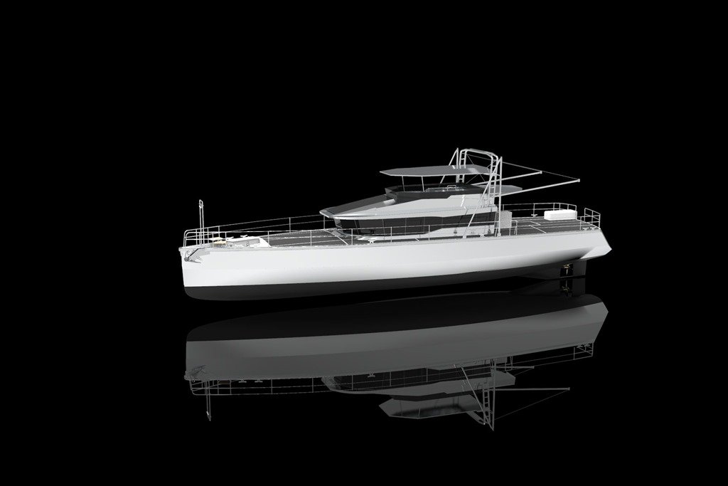
 1053 days of build time later, as most of you have likely seen in last week’s posting HERE, she finally left that temporary womb last Friday for a watery delivery into her permanent home with Mother Ocean last Saturday.
  As I write this blog post from the SkyBridge of our beloved Möbius, we have just finished our first week afloat tied up to the concrete dock wall inside the Antalya Free Zone Harbour.
 Tied up less than a meter in front of Möbius’ Bow.
 These two tugs are also the Fire Boats for the Harbour. And last night, they surprised and delighted us by bringing over a home made pizza just out of their oven! Can’t think of a better example of why we LOVE living with these awemazing people of Turkey.
 Tied up almost as closely to our Stern is this first of four Police boats which are being built by Ares Yachts here in the Free Zone for the government of Oman. These are a bit longer than us at about 26m but share many of the same basic attributes as our XPM-78 with all aluminum construction and built like the proverbial tank.
 We even have the same jet propulsion system though in our case just with our Tender and a single not these massive twin jet drives driven by two equally massive MAN diesel engines.
 One item that we do not share, YET! with these boats is that mount for a 50 cal machine gun. But rest assured that once I get my 3D printer setup one of my first projects will be to create a realistic enough looking plastic replica to produce a silhouette that will add to our “don’t mess with me!” look to any onlookers thinking of approaching us with mal intent!
 I took this shot of our neighborhood early this morning after the Argo B had left and the tugs were back in front of us. The weather has been truly spectacular for the past two weeks with daytime highs reaching 24C/77F and gloriously sunny clear blue skies with very little wind. Not a bad place to spend our first week afloat.
 One of the projects I did not have enough time to show you last week was the completion of our rather unique “Sidewinder” anchor roller assembly that Dennis and I came up with so let me show that to you now.
 I decided to make the two anchor rollers out of solid aluminium and didn’t take me long to design a 3D model of this in Autodesk Fusion 360 and create the 2D dimensioned drawings to machine them from.
 Aluminium is a dream to work with and the in house machine shop has a very good sized lathe that was easily able to machine the two anchor rollers out of a single blank of 200mm/8” OD aluminium round stock.
 I wanted to keep the anchor and the chain electrically isolated from the hull to reduce any corrosion problems and was able to do so with two details. One is this Black Delrin bushing which we press fit into each roller with a nice rolling fit for the 40mm/1.6” SS pin that each roller spins on.
 The second isolating detail was to machine these Teflon discs that get separate the sides of the rollers from the inside cheeks of the anchor roller assembly welded into the hull. Then a large SS end cap bolts on either end of the SS pin on the outside.
 Here is what that all looks like when assembled.
 For safety and quiet when pounding into big seas we very specifically designed the whole roller assembly to exactly match the shape of this 125kg/275lb Rocna anchor by obtaining a 3D model from Rocna to design with. The way our design works is that those flared out bottom edges you see in the photo above have been designed such that they exactly match up with the inside of the flukes of the Rocna when pulled aboard and thus the Rocna becomes one with the hull and will not budge no matter what Mother Nature throws at us. This creates not only a very tough and strong anchor mounting setup but also one that does not make any noise due to movement between the anchor and the roller assembly which is so common on many other boats we have run.
 So Nihat, Uğur and I spent quite a few hours with the anchor raised on a chain block that allowed us to get the position of the anchor just right and then layout the centers for each SS roller pin. Front pin and roller have been mounted here and we are laying out the location for the 2nd Aft roller.
 Uğur and I came up with this idea of building an extended 40mm carbide hole saw so that he could drill both cheeks in one go and keep the two holes for the SS roller pin on the same centerline. We lucked out finding the head of a 40mm carbide hole saw with its shank broken off and Uğur TIG welded a 200mm/8” long piece of 13mm/ 1/2” OD rod to it that we could chuck in my Milwaukee drill. Worked like a charm!
 With the rollers both installed we tested it all out with the 13mm / 1/2” chain and the Maxwell VWC4000 Windlass and did a bit of tweaking of the rollers final shape to capture the chain nicely so it stays aligned as the chain goes Out/In and doesn’t twist.
  Did not take us long to get to the Goldilocks Just Right point
  and “Rocky” was in his new home as solid as his name.
 Uğur and Nihat both gave it their thumbs up and so we knew it was good to go!
 Once the super slick, slippery and shiny silicone InterSleek was fully dry the last few underwater details could be attended to such as mounting the Red plastic prop on the Vetus 220kgf 300mm/12” Extended Run Time Bow Thruster.
 Which is capped off with its own Zinc to reduce any problems with corrosion due to the mix of dissimilar metals involved with its construction of Bronze, SS and AL.
 In keeping with our Darth Vader, lean & mean look, we decided to make the 100mm/4” Boot Stripe that makes the transition between the top of the Black InterSleek and the bare AL hull, be gloss Black as well and we are eXtremely happy with the result that emerged as the masking tape came off to reveal the final look.
 The final detail for the underwater portion of the hull was mounting the ten 125mm / 5” diameter Zinc anodes which keeps all the metal bits that are in contact with seawater all at the same potential voltage and eliminates the battery effect that would eat away at our precious Stainless Steel, AL and Bronze components.
  Being near the bottom of the Noble scale of metals, Zinc is what will erode instead and makes it easy to replace the zincs every few years when they get too worn away.
 We designed a very simple mounting system for the Zincs and Uğur had previously welded 80mm discs of 20mm / 3/4” thick AL to the hull with an M16 thread in the center for the SS M16 bolt that he is fastening this Zinc on the Rudder with.
 To ensure a good electrical connection for many years between the Zinc and the AL mounting disc, we coated those surfaces and the bolt with dielectric grease and then I followed along after Uğur and covered the SS bolt heads with some clear silicone to make it all the easier to remove and replace these zincs in a couple of years. I usually do this while the boat is in the water using my Hookah or Snuba system so these little details all help to make that job go quick and easy.
 With all these preparations of the below the waterline areas of the hull and everything removed from underneath, Möbius was ready for the arrival of “Big Bird” the yellow 72 wheel boat mover to arrive the next morning and carry her overland to the marina for launching.
 Another few details that we needed to look after before Launch Day were for the all important steering system and the Tiller Arm in particular. Similar to the Bow Rollers, last year I had designed this typically over engineered Tiller Arm in Fusion 360 and had it CNC milled out of a single block of aluminum.
 Here is a shot from almost a year ago when we first mounted the finished Tiller Arm to the 127mm / 5” OD solid AL Rudder Post.
 And here is a more recent shot of what it looks like with the two double acting Kobelt hydraulic steering cylinders in place.
 Such a massive Tiller Arm being powered by equally as beefy twin hydraulic cylinders, produces a LOT of force and so there needs to be some eXtremely strong and solid Tiller Arm Stops built in to stop the Tiller Arm when it goes hard over to each side. Fusion 360 to the rescue yet again to help me quickly design these Stops which Uğur and Nihat quickly fabricated and were ready to mount.
 After carefully testing out the Just Right position for each stop, they were able to drill the four holes in the AL Rudder Shelf and bolt down one Stop in either side of the Tiller Arm body. The SS bolt and lock nut allow us to adjust the final Stop position of the Tiller Arm once we are in the water and have the steering all working.
 I like to practice and live well by what I call “Readiness for the UneXpected” and in the case of our steering system that meant having multiple layers of fault tolerance for the Steering System. This starts with twin independent Kobelt 7080 hydraulic steering cylinders sized so that either one can fully steer the boat in the most adverse sea conditions.
 And if ALL of that should uneXpectedly fail, then we have this Kobelt manual hydraulic Steering Pump ……………
 ……….. that we can slide this Emergency Steering wheel onto and steer the boat the “old fashioned” way.
 And if ALL of that should somehow uneXpectedly fail we have THIS final layer of fault tolerance for our steering system; a completely independent and manual Emergency Tiller Arm.
 Can’t get too much more KISSS or Keep It Simple Smart & Safe than this; a 2m/6.5ft length of 80mm thick walled AL pipe that slides through the 20mm/ 3/4” thick plate we see Uğur bolting to the Tiller Arm body and then the pipe slides through a matching hole bored through the top of the Rudder Post.
  We attach a block and tackle setup on each side of the end of the Emergency Tiller which fasten to shackles mounted on stringers on the adjacent hull sides which allows us to move and lock the Rudder in any position we want.
 Turkish Turquoise Marble countertops got installed atop both Vent Boxes on the Aft Deck to create our Outdoor Galley.
 SS sink plumbed.
 And installed in the Starboard/Right side Vent Box.
 Plumbing connections all ready to connect to the sink; Red & Blue PEX lines with shut off valves for the Hot/Cold water to the sink faucet, Brass elbow for the sink’s drain and small Blue tube with the Black elbow to drain the water extracted by the Mist Eliminator grills in the Engine Room supply air duct.
 Orhan with his home made adaptor for his pneumatic caulking gun ……..
 ……. to get into some hard to reach spots around the Pilot House windows like these.
 Uğur prepping the nylon insert mounts for the Passarella on the Swim Platform and another on the Port side gate.
 Ever the ingenious one on Team ,Uğur came up with this brilliant DIY solution for mounting our Fire Hose in the HazMat Locker; an empty plastic spool of MIG welder wire!
 Which will rotate on this pipe mounted on the side of the HazMat Locker.
 With the Black Fire Nozzle mounted alongside. Any wonder why I just love working with this guy who has been with us from the very first day of the build?!!!
 More Uğur Goodness, on Saturday no less, as we designed and built this simple setup for propping the front 3 Solar Panels mounted on this hinged frame up in the horizontal position when we are on anchor.
 Two SS pipes that are hinged to the bottom of the Solar Panel frame and will fit into these Black Delrin collars Uğur machined which were then glued down to the aluminium floor with a SS set screw to lock them in place.
 We ended up with two primary circuit breaker panels; this one on the angled short wall on the Stbd/Right side of the Main Helm Station.
 And this larger one in the Corridor at the bottom of the stairs leading down from the SuperSalon to the Guest Cabin, Ships Office and Workshop/Engine Room.
 After months and months of preparation, Hilmi was finally able to bring it all together this past week by attaching these Black AL panel fronts with all the engraved labels onto the hinged access doors into each of these Circuit Breaker panels.
 The double paned 16mm thick glass window finally got installed in the Engine Room door this week which is a critical component to completely closing in the Engine Room in the case of a fire.
 And the gas lift cylinders have now all been installed on the Glass Deck Hatches which I designed and Naval built in house. Now just need to finish installing the rubber edge seals and the AL hatch handles and the deck is totally watertight!
 I can’t possibly do justice to explain the amount of work that Christine has done this past week alone on getting all our navigation and electronics in both Helm Stations all setup and working.
  What I can do though is to leave you with this shot from early this morning that does capture for me just how well we have succeeded in designing and building our new home with all of Team Möbius to meet the goal we set out over 5 years ago to blend in perfectly when in a commercial dock as apposed to a ‘yachty’ marina.


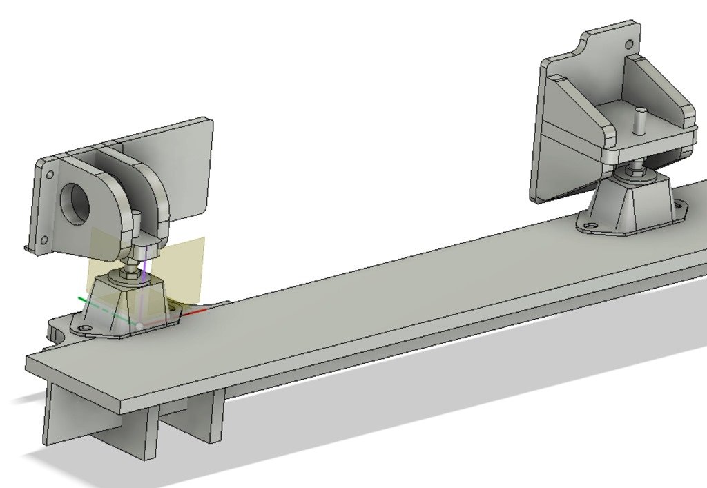


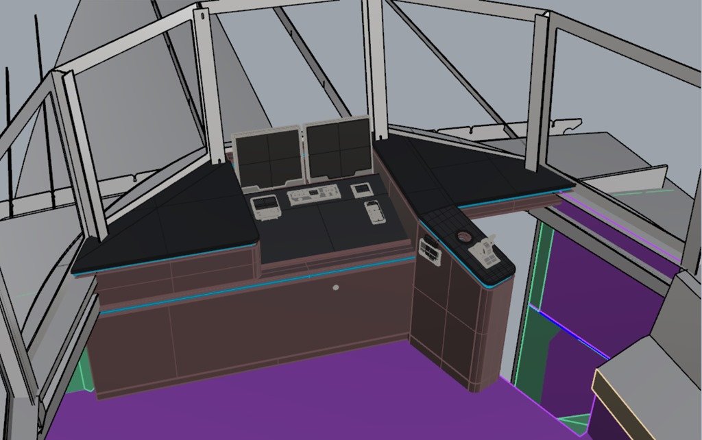


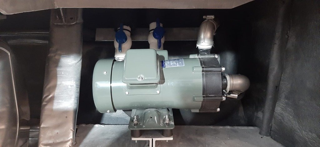
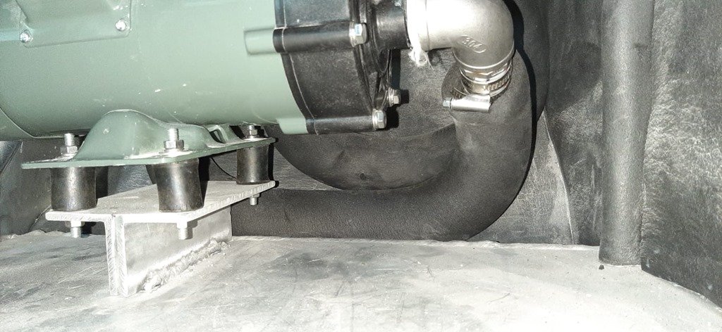


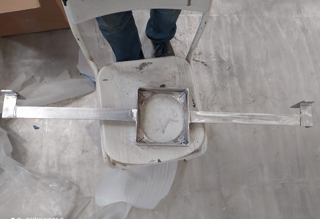

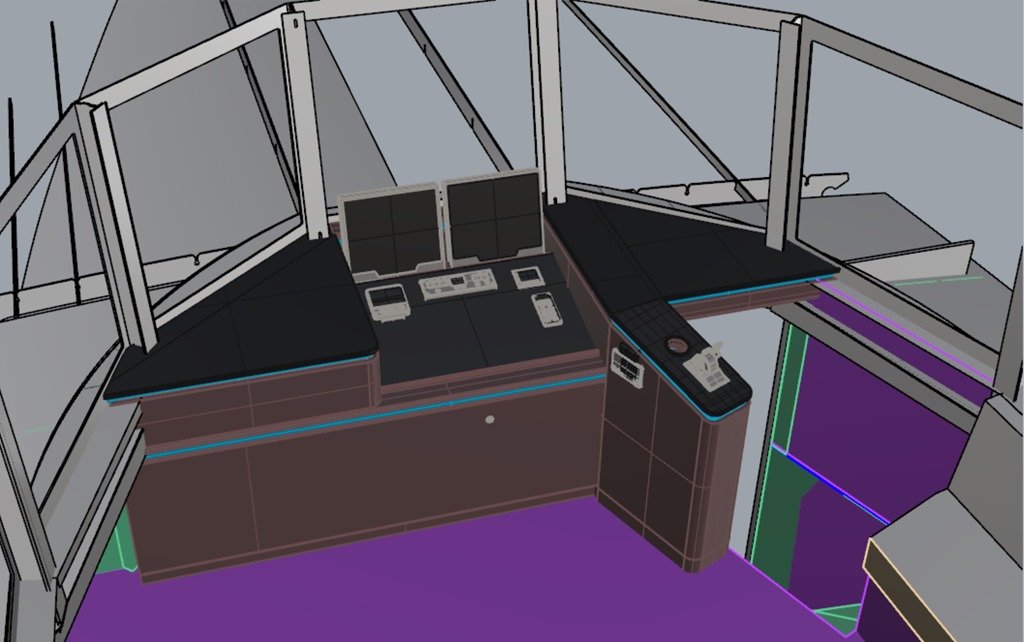


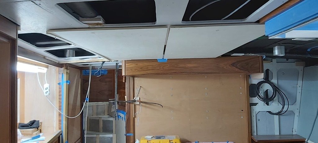


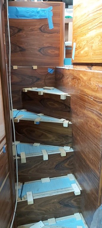


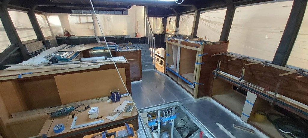


Recent Comments