

Aluminium Surgery with Dr. Wayne Lance Update 11 August, 2024
When we left off in last week’s “Constructive Deconstruction” update the interior of Lance’s box or what is often referred to as the Habitat, had been stripped pretty much naked after I had removed all the cabinetry, equipment and wiring of the original Horton ambulance. It was now down to quite literally just the “skin and bones” of the original box.
 Time to switch from deconstruction to surgery!
 It was quite amazing for me to discover that there was literally not a toothpick worth of wood in the entire Horton build. As you saw in the previous post, all the cabinetry was made from extruded aluminium framing and sheets of 13mm / 1/2” thick ACM (Aluminium Composite Material).
 And all of the box itself was built entirely from 50 mm / 2” square tubing.
 Which is “skinned” or covered with sheets of Xtremely thick 3.5mm / 0.138” thick AL plate. (think very thick HD cardboard box or car window glass)
I also discovered that there are no seams other than at the four outer corners of the box. All the side walls and roof are made from a single continuous sheet of thick aluminium which makes for a very beautiful box and NO leaks!
Another intriguing discovery I made was that this thick outer skin is not welded or riveted anywhere! Instead the skin is glued onto the frames using thick VHB (Very High Bond) adhesive tape. This way there is no direct contact between the aluminium skin and the frames which eliminates any chance of corrosion and provides a bit of a thermal break between the skin and the frames.  For example, if you look closely (click to expand any photo) you’ll see that there are no welds between the wall sheets and the frames. Note that the smaller pieces of aluminium L bar are welded to the frame but not to the outer skin.
This was also done to eliminate any warping of the huge continuous sheets of AL if they had been welded.
Redistributing External vs Internal Storage:
One of the great features that makes an ambulance such a great basis for building an eXtreme RV are all the externally accessible storage compartments located on both sides of the box.

There is one on each corner and on the drivers side there is a third one in the middle.
 You can see these compartments a bit better perhaps here in this screen shot of the 3D model (facing drivers side) I created to accurately document the original.
However, as we designed the new interior living space, we realized that we needed to have a better balance between the volume of this externally accessible storage space and that on the inside.
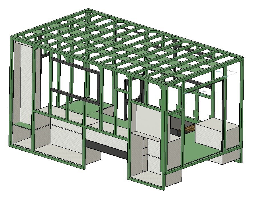 If you compare these two renders you can see the external storage compartments have been re-sized. Clearly some reduX surgery is needed on all four corners.
Switching to Surgery
 To get warmed up, I started with some minor surgery such as removing these ventilation fan covers. There were two of these on the drivers side and in our new layout these will both be covered by interior cabinetry and the lift bed and we’ll be putting in new ventilation and air conditioning.
 If you refer to the 3D model shots above you can see that the passenger rear corner compartment is going to be cut down the most as this is where the corner of the L-shaped settee will be.
 My circular saw with a carbide tipped aluminium cutting blade quickly cut out the upper portion.

And it was soon on its way to the growing collection of diamond plate aluminium that will be reused to build new compartments.
 The compartment on the opposite rear corner needed to be cut down in height and depth to allow the Queen bed to fit as it is raised and lowered.
 Here is a look from the outside with some of my weapons of mass deconstruction in the bottom.
 Moving on the drivers side front compartment, the section from the interior floor up to the ceiling will become the Head (toilet) so it needs to be cut down.
 The remaining portion of this exterior compartment will closed in and house all the electrical system components.
Now for some Reconstructive Surgery
 With the external compartments cut out I now started cutting the pieces needed to weld back in to close each compartment.
 Here is the new top for the PS Rear compartment after being carefully cut, filed and clamped to fit precisely inside the remaining vertical walls creating a tight fit along each edge to be welded.
 Then I could put in some tack welds to hold the new piece exactly square.
 And then weld each edge. I’m teaching myself to TIG weld so my skills still have a LONG ways to go and the welds are not pretty but I think they will be plenty strong enough. I’ve done some destructive testing of many practice welds to see if the welds would break and am able to produce welds that don’t.
 The new section on the DS Rear took a bit more time to fit and get just right.
 But I soon had its new vertical wall welded in.
 Followed by the new horizontal plate and that new compartment was all welded.
 Completing the Rear compartments.
 The new vertical wall of the future Electric Cabinet on the DS Front corner was a bit more challenging as I needed to extend the height of the old part I cut out.
 Worked out well in the end.
 and it was ready to be fitted in place. Worked out very well as I was able to reuse those two vertical slot bars to mount the bit Victron MultiPlus inverter charger.
 Along with the new floor plate and both were welded then fully welded in to finish off this new compartment.
 The mid compartment on the DS does not have any exterior doors and so I just cut out the top and side and left the rest of this lovely diamond plate in place that will form the bottom of a large interior cupboard.
 As you saw above I had welded in the new bottom section of the PS Rear compartment but I now needed to close in that large open upper section as will be a fully insulated interior wall in the new layout.
 Another contribution from the diamond plate collection and I had this new piece fitted for its new lease on life.
 Here is a look at the new version from the outside. This wall is a bit different than the other compartments as it had to be bolted in place rather than welded as it is right up against the painted aluminium frame and skin
With all these external compartments now all resized that should mark the end of the deconstruction phase and will be a wrap for this week folks.
I’m getting closer to catching you up to real time in the build and next week I’ll show you the process of fully insulating the walls and ceiling with PolyIso foam board. This will bring them up to about R-20 insulated value in the finished habitat or “Happytat” as one of my typos prompted me. Out work on renovating, building and living in our previous boats has taught us the multiple values of great insulation so we’re applying those lessons in this latest build.
Oh NO!!! What is he thinking???
 As a teaser to keep you coming back for more, does this photo help you guess what I’ve been doing in the past few days?
It’s a new and exciting phase of the build that I can’t wait to show you in the next few weeks and something exciting to show Gramma Christine when she gets back home from Florida on Thursday night.
Till then I hope this is proving to be fun and interesting to read and I really appreciate your doing so.
It would be especially helpful to get any of your suggestions for changes and improvements. As you may have noticed I’ve been playing around with sizing of the photos and text so let me know what you find best in terms of spacing, layout, etc. Text on the sides or text below the photos? Level of detail; too much/too little and so on.
Thanks and hope to see you back here again next Sunday.
-Wayne
Recent Comments