OK, I’m back from the detour we took here last week with the arrival of our two new Havapoo puppies “Zoe” and “Razz”. If you missed it you can read all about them HERE. They continue to entertain and delight us non stop as well as grow non stop so all is well with them.
In the last post on the build progress back on Sept. 8th called “We’re Floored” I left off having completed the installation of all the foil backed PolyIso Foam boards or PIF insulation in the walls, ceiling and floor and covering them with sheets of 4mm ACM or Aluminium Composite Material as per this photo at that stage. The floors were made of this Lance Club sandwich that starts on the bottom with the 4mm AL floor plates of the original Horton ambo box, then a 3mm layer of rubber matt, a 13mm/ .5 inch layer of AL foil faced PIF R3 insulation topped with a layer or 4mm ACM. The floor was now ready for the next step in its evolution; embedding all the runs of PEX tubing through which a heat transferring liquid that will flow, turning this into a thermostatically controlled heated floor. For those unfamiliar with it, PEX tubing is a cross-linked polyethylene pipe manufactured using extrusion method that creates infinite lengths of extremely strong and flexible tubing. It has been around for over 50 years and has largely replaced the use of copper and PVC pipes for plumbing in residential and commercial buildings. It is readily available in coils up to 500 feet and sizes from about 6mm/ 1/4” up to 2” with 1/2, 3/4 and 1 inch being the most popular. I have had great success using PEX for plumbing other projects over the years and it is pretty much the go to tubing for hydronic heated floors in any building. We used this for the floors in our previous boat Mobiüs and once you’ve had heated floors you never want to be without them again and this was one of the givens when we started to design Lance. I will also use PEX for all the plumbing of our hot and cold water systems in Lance so you’ll be seeing it quite often here as the build progresses. Our hydronic heated floors simply have loops of PEX tubing embedded into the flooring through which a heated solution of glycol (anti-freeze) and water flows and transfers the heat from the liquid into the flooring. This heat transfer fluid will be heated by the diesel fired boiler we have for our onboard Domestic Hot Water or DHW which makes it a very important bit of kit for our day to day living so you’ll also be seeing much more about this in coming update posts. We’ve decided to use the Oasis Zephyr 33k BTU model from International Thermal Research or ITR as this is the same company that made the boiler in my first boat “Learnativity” that worked very well and yes, I’m a wee bit biased as this is a Canadian company based out of Richmond near Vancouver BC where I lived and taught for many years. I had ordered three 100 foot long coils of 1/2 ınch ID PEX type A (more on that later) in Red and Blue for Hot and Cold water and White for the heated floor loops and I did some experimenting with different ways of embedding this tubing into the flooring I’d just installed in Lance. The PEX tubıng ıs 1/2 ID Insıde Dıameter and 5/8 ınch OD so I used a 5/8 ınch core box carbıde bıt ın my Bosch router and one for my smaller cordless Mılwaukee router to get ınto smaller spaces.
These bits cut a just right groove into the test pieces of the floor sandwich. I had also ordered a box of these special aluminium heated floor transfer plates that are typically used in plywood based radiant floors but I wasn’t satisfied with the way they fit. Even after some judicial flattening with a hammer these plates just would not lay completely flat and created an air gap that would not have been as effective in transferring the heat from the PEX tubing into the surrounding AL flooring, and this would have also created a slightly non flat surface for the finished floors which was also not acceptable. It would have worked OK to just press the PEX into the grooves but I wanted to maximize the heat transfer so I used some thick 5 mil aluminium ducting tape and carefully pressed this into the grooves. ….. and that gave me the Goldilocks just right fit I was seeking.
Planning for the heated floor began with laying it all out in the 3D model in Fusion 360 which I did several months ago starting with this sketch of the routing for the 1/2” PEX tubing. 3 Once again my 3D modelling for Lance paid off by allowing me to get the just right layout of the lengthwise running PEX tubes. Once I had the spacing and layout all worked out I simply used the “Sweep” function in Fusion 360 to follow the sketch line and create the model of the tubing itself. The minimum bend radius of this 1/2” PEX-A tubing is 6 times the 5/8” OD so 3.75” and I increased this to 4.5” for a bit of safety and that’s why there are those round abouts as each run of PEX makes the U-turn to go back the other direction as you see here. With all that planning in hand I used some 1” wide blue masking tape to lay out the location of the 1” wide eXtruded Aluminium or XAL cabinet framing that will be bolted to the floor so that I could be sure that the PEX tubing would not interfere with this. You can see that I traced out the center line of the PEX tubing with a felt pen to help me position the router. I cut out this jig from some scrap 5mm ACM from the original build and used this to guide the base of the router to make this sweeping omega shape for the U-turns at each end. To make sure that the open end of the Omega shaped jig was the proper distance I made this short piece to press fit between the two legs of the jig and then marked two lines where the actual PEX tube center lines of each leg should be. This made accurately positioning the jig very quick and easy. Once I had the jig precisely positioned to my felt pen marks, I secured it to the flooring with three short screws to hold it in position
Then with the outer edge of the base of the router pressed tightly against the inner edge of the jig I was able to guide the router bit along the just right track. I made three passes starting with a shallow first cut of about 5mm deep and
… worked up to the full depth of just over 5/8” which if you look closely you can see was just cutting into the thin bottom layer of AL on the ACM of the flooring. Quick test fit using a short piece of the PEX tubing and I was ready to go. Reposition the jig for the next cut …… …….. rinse …….. ….. and repeat ………. There were a few places where the base of the larger Bosch router were too big so I built a smaller jig and ……used my cordless Milwaukee router to cut those grooves. Used the same jig and router to cut these grooves where the PEX tubing enters and exits into the external compartment where the diesel boiler will be. And that completed all the router work and all was groovy. (sorry, couldn’t resist) Next I peeled off the protective layer of plastic with all the blue lines and arrows, from the ACM floor and started to press in the AL ducting tape to line each groove. The AL ducting tape is eXtremely sticky on the back but I was able to fold each 3” wide length in half, peel off the paper backing ……….. …….. and carefully set it into the bottom of the groove. Then I could use a combination of my index finger and .. The end of one of my vacuum nozzles that conveniently had just the right radius to press the sticky AL ducting tape onto the sides of the grooves. For the radiused U-turns I used the same technique to insert the folded tape lengths into the groove and then sliced the outer edge so I could bend the tape over and stick it tight against the ACM. Putting my weight on the plastic roller worked well to get the tape very flat and well adhered to the ACM. Ta Daaaa! All done and ready for the PEX tubing to be pressed in place. Where the PEX tubing enters and exits the mid Drivers Side external cabinet I needed to come up with a way of protecting the PEX from the edges of the AL holes I had drilled through. These plastic fittings are normally used for electrical conduit but they worked just perfect for both protecting the PEX and creating a watertight joint where they pass through. With the help of my (headless) Beautiful Bride and my trusty sledge hammer we were able to feed the PEX back and forth into the grooves and then back …..into the compartment where I could slide on the other parts of the fittings and tighten them snuggly in place. Worked out very well. Final step was to put AL ducting tape over the top of all the PEX tubes and the floor is now ready for the final layer of 4mm ACM to go on top and that is where I will pick up tomorrow morning to start another week working on Lance. So that’s a wrap for this week and hope you found it a bit interesting and will join me here again next week to see the next phase of putting in our finish flooring.
Thanks for your time and endurance reading all through this and please leave any questions and comments in the “Join the Discussion” box below.
Another week flies by and another month doing the same and another year for that matter! One of the many things I got wrong in my youth was the notion that time would seem to slow down a bit as we aged but the opposite seems to be the case. At least to me and I suspect many of you too. Not a bad thing other than how I could always use more time because my rate of progress and how long things take seems to be what slows down. Yet, forward progress is being made, albeit slower than I might like and this week I’ll show you how things have progressed with the insulation and installation of the final surface inside good ‘Ole Lance’s Happytat, the floor.
To the chagrin and no doubt consternation of my Brilliant Bestselling Author Bride, I’ll give away the ending with this photo just after just putting down the top layer of ACM Aluminium Composite Material for the heated floor. Going back to the beginning a bit, this is where we left off last week having installed all the PIF (PolyIso Foamboard) insulation and the ACM panels on the walks and ceiling. And going back ALL the way to January when we went and picked up Lance in Illinois, here is what the original floor and interior looked like. Prep work on the floor began with removing the vinyl diamond plate flooring and then the eXtremely recalcitrant aluminium track you see running down the center of the floor in the photo above. This track is what the collapsible Stryker ambulance stretcher rides on and locks it in place. For safety and security this 25mm/1” thick AL track is through bolted into the floor framing below with large high strength steel bolts. As you might imagine, the combination of aluminium floor plating, frames and track with steel bolts do not play nicely together chemically so they were all solidly seized and took quite a bit of persuasion to be removed but I eventually succeeded and could continue to remove the flooring. The floor material you see here is 13mm / 1/2” thick ACM that will make a great substrate to embed the 1/2” PEX tubing into the floor later to circulate the hot floor heating liquid through so I wanted to be able to reuse this huge continuous sheet. To do so I carefully cut through the ACM floor lengthwise along one side of the track’s slot using my cordless circular saw and a long straightedge to get a very straight edge that will later become a butt joint of the two halves in the new floor. You can see how clean and square an edge the carbide blade in the circular saw leaves on the ACM and will make for a smooth seamless transition between the two halves when I reinstall them later. The ACM flooring was through bolted to the 2” x 3” AL floor frames below but not glued in place so once I had all those bolts removed I could pry the ACM up to remove it.
I was then able to flip each half of the ACM floor up as you see here. When Horton Emergency Vehicles put in the floors in their ambulances, they first glue down rectangles of black tar like material similar to roofing material you can see on the Left here and then they lay down a continuous layer of 4mm / 3/32” rubber matt on top of that before they put in the 1/2” ACM. Several of the bolts fastening the ACM to the AL floor frames had sheered off when I was removing them so I brought out some of these Weapons of Mass Deconstruction to remove them. This shot as I’m removing one half of the floor gives you an idea just how large the original ACM flooring was. A single sheet about 4.25m / 14’ long by almost 2.4m x 8’ wide! When I removed the flooring I was delighted and relieved to find that the underlying AL floor plates and frames were in great condition. The only exception was that at some point in Lance’s previous life there had been a leak in the seals on the DS rear door which allowed some water to be trapped between the AL floor and the sheets of tar material causing a bit of corrosion in this area. So I spent several hours scraping off the tar matt in that rear DS corner to clean that all up. Final preparation for the new flooring began with trimming up the two halves of 1/2” ACM I had removed previously. In order to get a continuous straight tight joint down the middle I turned one half of the floor ACM end for end and resawed this edge to be perfectly straight. I dry fitted each half in place to get all the cut outs around the external storage compartments along each side and then slid the ACM halves back out and was finally ready to start installing the new flooring. First layer of the new flooring is this 1/2” thick PIF (PolyIso Foamboard) that is faced on both sides with AL foil. As you saw me do with the ACM above, I cut and fitted the PIF around all the compartment cut outs and soon had the first layer of the new flooring all in place. Next layer was the 1/2” ACM so I carefully laid that in place on top and used some lengths of 2×2” square AL tubing for straight edges to compress the ACM to the PIF and make the floor flat and seamless. That center joint between the two halves of ACM worked out very well as you can see here up at the front wall. I cut new pieces of 1/2” ACM for areas I had cut out the original external compartments and glued them in place. This new ACM is the same as the original, just has AL faces that are white. If you look along the upper left edge of the ACM you will see where the original slot for the stretcher track has ended up after I turned the ACM 180 degrees and now has a new piece of white faced ACM to fill this in. The final layer before I can route the grooves for the 1/2” PEX tubing for the heated floors is a layer of new 4mm ACM. Pretty straightforward; 4×8’ sheets are trimmed to fit around all edges and then the protective plastic is peeled off the bottom surface. The same DAP/Weldwood Landau HHR contact adhesive you saw being used last week on the walls and ceiling is poured into the electric HVLP spray gun. Top and bottom AL surfaces are covered with a thin film of this contact adhesive. …… and with Christine’s help, carefully lined up and lowered the gooey panels into their final resting place as you only get one shot with contact adhesive that grips for good immediately. Which takes us back to the end were I began this week’s update so I’m going to leave off here for this week and pick up next.
As per all those blue arrows confirm, forward progress is being made.
Just to review (quiz is on Friday) the layer cake floor starts with the solid AL floor panels, then a layer of black rubber, then 1/2” foil faced PIF, 1/2” ACM original and the top layer of new 4mm ACM.
For those wondering, this layered sandwich floor is bolted and glued to the AL floor frames of the 8ft Wide x 14ft Long x 6.5ft High rectangular “cage” which the whole frame of Lance’s Happytat is build upon. These frame members are made from 2×2, 2×3 and 2×4 inch rectangular thick walled AL tubing which in turn is bolted to 1×4” solid AL bars that are then rubber mounted to the steel frame of the Kenworth truck chassis. So no need for any concern about strength of stiffness with our dear Xambo Lance!
My congratulations and appreciation for those who have made it this far and hope you’ll return for more next week.
If you have any energy left please do leave any questions and comments in the “Join the Discussion” box below.
For many years now, Christine and I have often joked about how we’ve learned to build our boats and now our RV to be quite like a thermos bottle because we’ve learned just while the cost can be high the benefits pay us back in many ways for many years. There is the obvious benefits of helping to maintain the interior temperatures just right no matter where we roam from hot tropical weather to snowy colder climes, but the more insulated the spaces are the less energy it takes to heat or cool them so our HVAC (Heating Ventilation Air Conditioning) systems can be smaller and more efficient and cost effective. The somewhat less obvious benefit is that more insulation and careful installation also dramatically reduces noise transfer so our little thermos bottle homes have also been eXtremely quiet inside which we have come to appreciate more and more each year.
So I’ve been smiling more than usual of late as I’ve been reminded of an old joke about the conundrum of thermos bottles; they keep hot things hot and cold things cold BUT how the heck do they know which to do??!!
Still cracks me up and you can just consider this part of my vast collection of Dad/Grampa jokes my family can tell you about but lucky for you I will NOT get started on more for now.
Thermos is the famous name of the company that first started making these “ThermoFix” bottles in 1904 and technically these are known as a Dewar flask which use vacuum in the walls to reduce the speed of heat transfer to automagically keep hot things hot and cold things cold, no technology required!
photo by Erik Holmén / Nordiska museet
Vacuum panels would be a bit too much cost and trouble so I am using rigid foam board instead for insulating Lance and so I’ve been smiling away the past few weeks as I went about insulating Lance’s walls, ceiling and floor which is this week’s theme as you’ve gathered by now.
After many hours of research on the different types of insulation from rigid foam boards to spay on foam to real and synthetic forms of wool and many others, I decided to use sheets closed-cell polyisocyanurate (polyiso) or PIF rigid foam boards as they best met our criteria and priorities and is the Goldilocks just right insulation for us and Lance. I have had very good experiences using Sika products on our boats and so I chose these Rmax R-Matte® Plus-3 polyiso boards which are made by Sika also have the big benefit of being available at our local Home Depot store. These PIF is the most expensive of the various foam boards but as per the tables here and above this is for good reason as they have the highest R-value.
Another of the Goldilocks factors is that these R-Matte boards are faced with aluminium foil on both sides which adds to their insulation capabilities. One side of the board has a raw AL reflective surface, the other side has been coated to have a non reflective white matte surface. Boards can be installed with either the silver or white side out and for additional radiant barrier properties the silver side can be installed facing the air space if one exists. As you can see here the final Goldilocks factor that sealed the deal to go with these PolyIso PIF rigid foam boards is that they were also going to be the easiest to install as their thicknesses exactly matched the depths of the cavities in the walls and ceilings created by the 2” square AL tube frames.
The ceiling cavities were going to be the most challenging because there were three parallel sets of AL plates running the full length of the ceiling to strengthen and stiffen the ceiling frame. This meant I could not just fit a full 8 foot length of foam board into each cavity which would have made the installation go eXtremely fast. Instead the longest single piece of foam board I could fit into one of the open areas between the reinforcing plates plates was about 50cm/20” long.
So this turned into a supersized version of Tetris as had to put in each of these short pieces into the opening and then slide it sideways through the opening between the outer skin and the reinforcing plates. The 2” gap was a bit too perfect of a fit for the 2” thick PIF boards and so they needed some force to get them to slide across. The foam is very fragile of course so I made up this “persuader” from a length of 2” square AL tube which just fit into the cavity and covered the full thickness of the end of the foam and I could tap them through the opening. Other reinforcements in the form of these 45 degree corner braces that were welded into many places on both the walls and ceiling and this made the whole cut and fit process a bit more finicky and time consuming. Another Goldilocks factor in choosing to use these Sika PIF boards was that they cut very cleanly with a carbide saw blade and so I was able to get very clean square edges using a combination of my table saw and cut off saw. I wanted to get a good press fit everywhere the foam fit into these bays and of course each bay was just a bit different width so I had to measure and cut each one individually and cut the 45 degree corners where needed so it took me several days to complete the whole process but well worth the time to get close fits throughout with no need for any adhesive or spray in foam filler. Here I am closing in on the finish line for the ceiling insulation, just 2+ more rows to go! Whew! Ceiling all done, now onto the walls. I started with the walls in the DS Drivers Side front corner and worked my way out from there. There was still a good bit of fitting required as the length and width of each piece of PIF was different but it all went well. The blank space here is for the windows you saw me install in the previous post. Rinse and Repeat as they say and I worked my way around all four walls. It was probably a bit of my typical “over engineering” but once all the first layer of 2” PIF boards were installed I then sealed over each joint between the PIF and the AL frames with thick aluminium tape.
Second Layer of PIF
Now on to the second layer of 1” PIF insulation I added on top of the first layer of 2” foam boards. This went MUCH faster of course as I could now put up large sheets starting with this first full 4 ft by 8 ft sheet in the DS front corner. My adjustable support poles and lengths of extruded aluminium bars came in very handy to glue each panel to the ceiling. More rinse and repeat cycles and it didn’t take long to finish gluing this 1” PIF to the whole ceiling.
You may note that I installed the first 2” thick layer with the reflective foil side facing up against the AL ceiling skin panels and then put the final 1” layer with the reflective side facing down into the open interior spaces. The ceiling/roof skin panels will be mostly shaded being covered with solar panels but some will get through and so the top foil layer will help reflect this heat back out. On the inside, the reflective foil reflects the heat back into the interior where we want it.
ACM: The Final Layer
To fully finish the insulation of the ceiling and walls I glued in a third layer of ACM or Aluminium Composite Material. I’ve referred to ACM in previous posts and it is a truly phenomenal industrial grade product that does not seem to have become as well known in North America as it is in Europe and Asia.
ACM comes in thicknesses from 3 to 30 mm .125 to 1 1/2 inch or more and we found ACM in Türkiye when we were building our previous boat Möbius and used it extensively with great success. It was therefore an easy choice for us as the Goldilocks material for finishing off Lance’s ceiling and walls. As per this illustration, ACM is two outer layers of thin aluminium with a layer of polyethylene sandwiched between. It comes in pretty much any colour you want but we stuck with the most common white. It is similar to aluminium to work with using regular carbide tipped saw blades, router bits, etc. It can also be tapped with threads and holds threaded rivet nuts very well so makes for a great substrate for attaching hardware, wall panels and anything you’d like. Each surface is eXtremely flat and covered with a tough outer coloured layer that can also include textures for things like wood grain.
ACM comes in 2440 x 1220 mm sheets, close to 4ft x 8ft and the sheets are very precise even thickness and very flat fine finish. Our ACM is 3 and 6 mm 1/8-1/4” thick, white both sides. Both sides of each panel have a clear protective layer of plastic that has lines and arrows on to help when laying out. This protects the surfaces from scratches and overspray during the build and then is easily removed when you’re all done or when you need to apply adhesive to one side as you will see below.
ACM is a favorite material for road signs and advertisement boards so is quite widely available from industrial supply houses and we were able to find an supplier in the Portland area and order about 15 sheets for Lance and other future projects.
On her drive down from BC back in May, Christine stopped in Portland to pick them up and we soon had them safely stored in our workshop here in Klamath Falls. Before I started to install the 1 inch thick 2nd layer of PIF on the walls, I started installing the ACM panels on the ceiling because I wanted to foam on the walls to butt up against this. Peeled off the protective plastic layer from one side and …. ….. sprayed it and the ceiling with contact adhesive specifically made for this type of application. A quick note of caution for any others doing similar jobs or gluing in upholstery in ceilings and walls, you do NOT want to use regular contact cement or the commonly used 3M spray on version as these will NOT hold up over time. I’m aware of three professional van conversion and expedition vehicle manufacturers who have found this out the hard way when their panels have separated and fallen down on their builds when the owners were out using these vehicles. A hard and expen$ive lesson!
The problem with these kinds of contact cement adhesives as I understand it is that they don’t hold up in higher heat conditions such as what you find on the ceiling of vehicles out in the sun. DAP Weldwood makes a contact adhesive called “Landau Top & Trim HHR Solvent Type Spray Grade” that is specifically for this application so that’s what we have been using. Also available in these aerosol spray cans for smaller jobs but I just used a cheap $77 electric HVLP spray gun from Harbor Freight which worked very well. Same basic technique that you saw above for the 1” PIF panels, I used lengths of extruded AL and my adjustable support poles to clamp each panel in place. Goes very quickly when you are working with these larger panels. Ceiling and front wall fully clad in ACM, now on to the walls. Same as with the ceiling, I glued on the second layer of 1 inch thick PIF board to all the walls and sealed all their seams with AL tape. Then I could cut all the ACM panels for the walls, spray both wall and ACM panel surfaces with the special DAP Landau Top & Trim HHR adhesive…
…. and glue the ACM to all the walls. Last surfaces were the external access storage areas and these were first covered with 1 or 2” PIF and their seams taped and ready to be covered in the final layer of ACM. Whew! I will admit to being what Christine calls a Pooped Pirate but feels good to reach this point.
Next I’m on to installing the flooring and preparing for installing all the PEX tubing as these will be all hydronic heated floors, but that will have to wait for next week’s installment.
Till then my condolences to any who have made it this far and mostly my eXtremely sincere thanks for coming along for this ride.
Be sure to add your comments and questions in the “Join the Discussion” box below and I’ll be back same time, same channel with next week’s update.
When we left off in last week’s “Constructive Deconstruction” update the interior of Lance’s box or what is often referred to as the Habitat, had been stripped pretty much naked after I had removed all the cabinetry, equipment and wiring of the original Horton ambulance. It was now down to quite literally just the “skin and bones” of the original box.
Time to switch from deconstruction to surgery!
It was quite amazing for me to discover that there was literally not a toothpick worth of wood in the entire Horton build. As you saw in the previous post, all the cabinetry was made from extruded aluminium framing and sheets of 13mm / 1/2” thick ACM (Aluminium Composite Material).
And all of the box itself was built entirely from 50 mm / 2” square tubing.
Which is “skinned” or covered with sheets of Xtremely thick 3.5mm / 0.138” thick AL plate. (think very thick HD cardboard box or car window glass)
I also discovered that there are no seams other than at the four outer corners of the box. All the side walls and roof are made from a single continuous sheet of thick aluminium which makes for a very beautiful box and NO leaks! Another intriguing discovery I made was that this thick outer skin is not welded or riveted anywhere! Instead the skin is glued onto the frames using thick VHB (Very High Bond) adhesive tape. This way there is no direct contact between the aluminium skin and the frames which eliminates any chance of corrosion and provides a bit of a thermal break between the skin and the frames. For example, if you look closely (click to expand any photo) you’ll see that there are no welds between the wall sheets and the frames. Note that the smaller pieces of aluminium L bar are welded to the frame but not to the outer skin.
This was also done to eliminate any warping of the huge continuous sheets of AL if they had been welded.
Redistributing External vs Internal Storage:
One of the great features that makes an ambulance such a great basis for building an eXtreme RV are all the externally accessible storage compartments located on both sides of the box.
There is one on each corner and on the drivers side there is a third one in the middle.
You can see these compartments a bit better perhaps here in this screen shot of the 3D model (facing drivers side) I created to accurately document the original.
However, as we designed the new interior living space, we realized that we needed to have a better balance between the volume of this externally accessible storage space and that on the inside.
If you compare these two renders you can see the external storage compartments have been re-sized. Clearly some reduX surgery is needed on all four corners.
Switching to Surgery
To get warmed up, I started with some minor surgery such as removing these ventilation fan covers. There were two of these on the drivers side and in our new layout these will both be covered by interior cabinetry and the lift bed and we’ll be putting in new ventilation and air conditioning.
If you refer to the 3D model shots above you can see that the passenger rear corner compartment is going to be cut down the most as this is where the corner of the L-shaped settee will be.
My circular saw with a carbide tipped aluminium cutting blade quickly cut out the upper portion.
And it was soon on its way to the growing collection of diamond plate aluminium that will be reused to build new compartments.
The compartment on the opposite rear corner needed to be cut down in height and depth to allow the Queen bed to fit as it is raised and lowered.
Here is a look from the outside with some of my weapons of mass deconstruction in the bottom.
Moving on the drivers side front compartment, the section from the interior floor up to the ceiling will become the Head (toilet) so it needs to be cut down.
The remaining portion of this exterior compartment will closed in and house all the electrical system components.
Now for some Reconstructive Surgery
With the external compartments cut out I now started cutting the pieces needed to weld back in to close each compartment.
Here is the new top for the PS Rear compartment after being carefully cut, filed and clamped to fit precisely inside the remaining vertical walls creating a tight fit along each edge to be welded.
Then I could put in some tack welds to hold the new piece exactly square.
And then weld each edge. I’m teaching myself to TIG weld so my skills still have a LONG ways to go and the welds are not pretty but I think they will be plenty strong enough. I’ve done some destructive testing of many practice welds to see if the welds would break and am able to produce welds that don’t.
The new section on the DS Rear took a bit more time to fit and get just right.
Followed by the new horizontal plate and that new compartment was all welded.
Completing the Rear compartments.
The new vertical wall of the future Electric Cabinet on the DS Front corner was a bit more challenging as I needed to extend the height of the old part I cut out.
Worked out well in the end.
and it was ready to be fitted in place. Worked out very well as I was able to reuse those two vertical slot bars to mount the bit Victron MultiPlus inverter charger.
Along with the new floor plate and both were welded then fully welded in to finish off this new compartment.
The mid compartment on the DS does not have any exterior doors and so I just cut out the top and side and left the rest of this lovely diamond plate in place that will form the bottom of a large interior cupboard.
As you saw above I had welded in the new bottom section of the PS Rear compartment but I now needed to close in that large open upper section as will be a fully insulated interior wall in the new layout.
Another contribution from the diamond plate collection and I had this new piece fitted for its new lease on life.
Here is a look at the new version from the outside. This wall is a bit different than the other compartments as it had to be bolted in place rather than welded as it is right up against the painted aluminium frame and skin
With all these external compartments now all resized that should mark the end of the deconstruction phase and will be a wrap for this week folks.
I’m getting closer to catching you up to real time in the build and next week I’ll show you the process of fully insulating the walls and ceiling with PolyIso foam board. This will bring them up to about R-20 insulated value in the finished habitat or “Happytat” as one of my typos prompted me. Out work on renovating, building and living in our previous boats has taught us the multiple values of great insulation so we’re applying those lessons in this latest build.
Oh NO!!! What is he thinking???
As a teaser to keep you coming back for more, does this photo help you guess what I’ve been doing in the past few days?
It’s a new and exciting phase of the build that I can’t wait to show you in the next few weeks and something exciting to show Gramma Christine when she gets back home from Florida on Thursday night.
Till then I hope this is proving to be fun and interesting to read and I really appreciate your doing so.
It would be especially helpful to get any of your suggestions for changes and improvements. As you may have noticed I’ve been playing around with sizing of the photos and text so let me know what you find best in terms of spacing, layout, etc. Text on the sides or text below the photos? Level of detail; too much/too little and so on.
Thanks and hope to see you back here again next Sunday.


 The floors were made of this Lance Club sandwich that starts on the bottom with the 4mm AL floor plates of the original Horton ambo box, then a 3mm layer of rubber matt, a 13mm/ .5 inch layer of AL foil faced PIF R3 insulation topped with a layer or 4mm ACM.
  For those unfamiliar with it, PEX tubing is a cross-linked polyethylene pipe manufactured using extrusion method that creates infinite lengths of extremely strong and flexible tubing. It has been around for over 50 years and has largely replaced the use of copper and PVC pipes for plumbing in residential and commercial buildings. It is readily available in coils up to 500 feet and sizes from about 6mm/ 1/4” up to 2” with 1/2, 3/4 and 1 inch being the most popular.
  I have had great success using PEX for plumbing other projects over the years and it is pretty much the go to tubing for hydronic heated floors in any building. We used this for the floors in our previous boat Mobiüs and once you’ve had heated floors you never want to be without them again and this was one of the givens when we started to design Lance. I will also use PEX for all the plumbing of our hot and cold water systems in Lance so you’ll be seeing it quite often here as the build progresses.
  Our hydronic heated floors simply have loops of PEX tubing embedded into the flooring through which a heated solution of glycol (anti-freeze) and water flows and transfers the heat from the liquid into the flooring. This heat transfer fluid will be heated by the diesel fired boiler we have for our onboard Domestic Hot Water or DHW which makes it a very important bit of kit for our day to day living so you’ll also be seeing much more about this in coming update posts.
  We’ve decided to use the Oasis Zephyr 33k BTU model from International Thermal Research or ITR as this is the same company that made the boiler in my first boat “Learnativity” that worked very well and yes, I’m a wee bit biased as this is a Canadian company based out of Richmond near Vancouver BC where I lived and taught for many years.
  The PEX tubıng ıs 1/2 ID Insıde Dıameter and 5/8 ınch OD so I used a 5/8 ınch core box carbıde bıt ın my Bosch router and
  one for my smaller cordless Mılwaukee router to get ınto smaller spaces.
 These bits cut a just right groove into the test pieces of the floor sandwich.
  I had also ordered a box of these special aluminium heated floor transfer plates that are typically used in plywood based radiant floors but I wasn’t satisfied with the way they fit.
  Even after some judicial flattening with a hammer these plates just would not lay completely flat and created an air gap that would not have been as effective in transferring the heat from the PEX tubing into the surrounding AL flooring, and this would have also created a slightly non flat surface for the finished floors which was also not acceptable.
  It would have worked OK to just press the PEX into the grooves but I wanted to maximize the heat transfer so I used some thick 5 mil aluminium ducting tape and carefully pressed this into the grooves.
  ….. and that gave me the Goldilocks just right fit I was seeking.
 Planning for the heated floor began with laying it all out in the 3D model in Fusion 360 which I did several months ago starting with this sketch of the routing for the 1/2” PEX tubing. 3
  Once again my 3D modelling for Lance paid off by allowing me to get the just right layout of the lengthwise running PEX tubes.
  Once I had the spacing and layout all worked out I simply used the “Sweep” function in Fusion 360 to follow the sketch line and create the model of the tubing itself. The minimum bend radius of this 1/2” PEX-A tubing is 6 times the 5/8” OD so 3.75” and I increased this to 4.5” for a bit of safety and that’s why there are those round abouts as each run of PEX makes the U-turn to go back the other direction as you see here.
  With all that planning in hand I used some 1” wide blue masking tape to lay out the location of the 1” wide eXtruded Aluminium or XAL cabinet framing that will be bolted to the floor so that I could be sure that the PEX tubing would not interfere with this. You can see that I traced out the center line of the PEX tubing with a felt pen to help me position the router.
  I cut out this jig from some scrap 5mm ACM from the original build and used this to guide the base of the router to make this sweeping omega shape for the U-turns at each end.
  To make sure that the open end of the Omega shaped jig was the proper distance I made this short piece to press fit between the two legs of the jig and then marked two lines where the actual PEX tube center lines of each leg should be. This made accurately positioning the jig very quick and easy.
  Once I had the jig precisely positioned to my felt pen marks, I secured it to the flooring with three short screws to hold it in position
 Then with the outer edge of the base of the router pressed tightly against the inner edge of the jig I was able to guide the router bit along the just right track.
  I made three passes starting with a shallow first cut of about 5mm deep and
 Quick test fit using a short piece of the PEX tubing and I was ready to go.
  Reposition the jig for the next cut ……
  …….. rinse ……..
  ….. and repeat ……….
  There were a few places where the base of the larger Bosch router were too big so I built a smaller jig and
  ……used my cordless Milwaukee router to cut those grooves.
  Used the same jig and router to cut these grooves where the PEX tubing enters and exits into the external compartment where the diesel boiler will be.
  And that completed all the router work and all was groovy. (sorry, couldn’t resist)
  Next I peeled off the protective layer of plastic with all the blue lines and arrows, from the ACM floor and started to press in the AL ducting tape to line each groove.
  The AL ducting tape is eXtremely sticky on the back but I was able to fold each 3” wide length in half, peel off the paper backing ………..
  …….. and carefully set it into the bottom of the groove.
  Then I could use a combination of my index finger and ..
  The end of one of my vacuum nozzles that conveniently had just the right radius to press the sticky AL ducting tape onto the sides of the grooves.
  For the radiused U-turns I used the same technique to insert the folded tape lengths into the groove and then sliced the outer edge so I could bend the tape over and stick it tight against the ACM.
  Putting my weight on the plastic roller worked well to get the tape very flat and well adhered to the ACM.
  Ta Daaaa! All done and ready for the PEX tubing to be pressed in place.
  Where the PEX tubing enters and exits the mid Drivers Side external cabinet I needed to come up with a way of protecting the PEX from the edges of the AL holes I had drilled through.
  These plastic fittings are normally used for electrical conduit but they worked just perfect for both protecting the PEX and creating a watertight joint where they pass through.
  With the help of my (headless) Beautiful Bride and my trusty sledge hammer we were able to feed the PEX back and forth into the grooves and then back
  …..into the compartment where I could slide on the other parts of the fittings and tighten them snuggly in place.
  Worked out very well.
  Final step was to put AL ducting tape over the top of all the PEX tubes and the floor is now ready for the final layer of 4mm ACM to go on top and that is where I will pick up tomorrow morning to start another week working on Lance.

 Going back to the beginning a bit, this is where we left off last week having installed all the PIF (PolyIso Foamboard) insulation and the ACM panels on the walks and ceiling.
  And going back ALL the way to January when we went and picked up Lance in Illinois, here is what the original floor and interior looked like.
  Prep work on the floor began with removing the vinyl diamond plate flooring and then the eXtremely recalcitrant aluminium track you see running down the center of the floor in the photo above. This track is what the collapsible Stryker ambulance stretcher rides on and locks it in place. For safety and security this 25mm/1” thick AL track is through bolted into the floor framing below with large high strength steel bolts.
 The floor material you see here is 13mm / 1/2” thick ACM that will make a great substrate to embed the 1/2” PEX tubing into the floor later to circulate the hot floor heating liquid through so I wanted to be able to reuse this huge continuous sheet. To do so I carefully cut through the ACM floor lengthwise along one side of the track’s slot using my cordless circular saw and a long straightedge to get a very straight edge that will later become a butt joint of the two halves in the new floor.
  You can see how clean and square an edge the carbide blade in the circular saw leaves on the ACM and will make for a smooth seamless transition between the two halves when I reinstall them later.
  The ACM flooring was through bolted to the 2” x 3” AL floor frames below but not glued in place so once I had all those bolts removed I could pry the ACM up to remove it.
 I was then able to flip each half of the ACM floor up as you see here.
  Several of the bolts fastening the ACM to the AL floor frames had sheered off when I was removing them so I brought out some of these Weapons of Mass Deconstruction to remove them.
  This shot as I’m removing one half of the floor gives you an idea just how large the original ACM flooring was. A single sheet about 4.25m / 14’ long by almost 2.4m x 8’ wide!
  So I spent several hours scraping off the tar matt in that rear DS corner to clean that all up.
  Final preparation for the new flooring began with trimming up the two halves of 1/2” ACM I had removed previously. In order to get a continuous straight tight joint down the middle I turned one half of the floor ACM end for end and resawed this edge to be perfectly straight.
  I dry fitted each half in place to get all the cut outs around the external storage compartments along each side and then slid the ACM halves back out and was finally ready to start installing the new flooring.
  First layer of the new flooring is this 1/2” thick PIF (PolyIso Foamboard) that is faced on both sides with AL foil.
  As you saw me do with the ACM above, I cut and fitted the PIF around all the compartment cut outs and soon had the first layer of the new flooring all in place.
  Next layer was the 1/2” ACM so I carefully laid that in place on top and used some lengths of 2×2” square AL tubing for straight edges to compress the ACM to the PIF and make the floor flat and seamless.
  That center joint between the two halves of ACM worked out very well as you can see here up at the front wall.
  I cut new pieces of 1/2” ACM for areas I had cut out the original external compartments and glued them in place. This new ACM is the same as the original, just has AL faces that are white.
  If
If The final layer before I can route the grooves for the 1/2” PEX tubing for the heated floors is a layer of new 4mm ACM. Pretty straightforward; 4×8’ sheets are trimmed to fit around all edges and then the protective plastic is peeled off the bottom surface.
  The same DAP/Weldwood Landau HHR contact adhesive you saw being used last week on the walls and ceiling is poured into the electric HVLP spray gun.
  Top and bottom AL surfaces are covered with a thin film of this contact adhesive.
  …… and with Christine’s help, carefully lined up and lowered the gooey panels into their final resting place as you only get one shot with contact adhesive that grips for good immediately.
  Which takes us back to the end were I began this week’s update so I’m going to leave off here for this week and pick up next.


 Instead the longest single piece of foam board I could fit into one of the open areas between the reinforcing plates plates was about 50cm/20” long.
 The 2” gap was a bit too perfect of a fit for the 2” thick PIF boards and so they needed some force to get them to slide across. The foam is very fragile of course so I made up this “persuader” from a length of 2” square AL tube which just fit into the cavity and covered the full thickness of the end of the foam and I could tap them through the opening.
  Other reinforcements in the form of these 45 degree corner braces that were welded into many places on both the walls and ceiling and this made the whole cut and fit process a bit more finicky and time consuming.
  Another Goldilocks factor in choosing to use these Sika PIF boards was that they cut very cleanly with a carbide saw blade and so I was able to get very clean square edges using a combination of my table saw and cut off saw.
  I wanted to get a good press fit everywhere the foam fit into these bays and of course each bay was just a bit different width so I had to measure and cut each one individually and cut the 45 degree corners where needed so it took me several days to complete the whole process but well worth the time to get close fits throughout with no need for any adhesive or spray in foam filler.
  Here
Here Whew! Ceiling all done, now onto the walls.
  I started with the walls in the DS Drivers Side front corner and worked my way out from there.
  There was still a good bit of fitting required as the length and width of each piece of PIF was different but it all went well. The blank space here is for the windows you saw me install in the previous post.
  Rinse and Repeat as they say and I worked my way around all four walls.
  It
It Now on to the second layer of 1” PIF insulation I added on top of the first layer of 2” foam boards. This went MUCH faster of course as I could now put up large sheets starting with this first full 4 ft by 8 ft sheet in the DS front corner. My adjustable support poles and lengths of extruded aluminium bars came in very handy to glue each panel to the ceiling.
  More rinse and repeat cycles and it didn’t take long to finish gluing this 1” PIF to the whole ceiling.
 As per this illustration, ACM is two outer layers of thin aluminium with a layer of polyethylene sandwiched between. It comes in pretty much any colour you want but we stuck with the most common white.
 Both
Both
 Before I started to install the 1 inch thick 2nd layer of PIF on the walls, I started installing the ACM panels on the ceiling because I wanted to foam on the walls to butt up against this.
  Peeled off the protective plastic layer from one side and ….
  …..
…..
 Also available in these aerosol spray cans for smaller jobs but I just used a cheap $77 electric HVLP spray gun from Harbor Freight which worked very well.
  Same basic technique that you saw above for the 1” PIF panels, I used lengths of extruded AL and my adjustable support poles to clamp each panel in place.
  Goes very quickly when you are working with these larger panels.
  Ceiling and front wall fully clad in ACM, now on to the walls.
  Same as with the ceiling, I glued on the second layer of 1 inch thick PIF board to all the walls and sealed all their seams with AL tape.
  Then I could cut all the ACM panels for the walls, spray both wall and ACM panel surfaces with the special DAP Landau Top & Trim HHR adhesive…
 ….
…. Last surfaces were the external access storage areas and these were first covered with 1 or 2” PIF and their seams taped and ready to be covered in the final layer of ACM.


 You can see these compartments a bit better perhaps here in this screen shot of the 3D model (facing drivers side) I created to accurately document the original.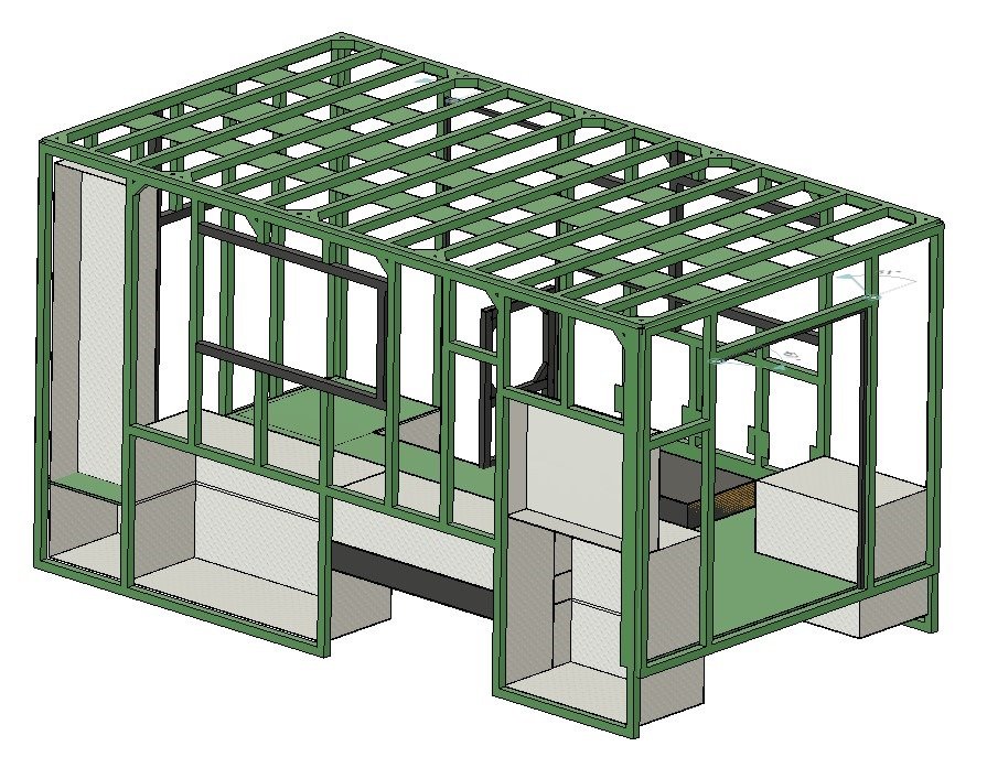
 To get warmed up, I started with some minor surgery such as removing these ventilation fan covers. There were two of these on the drivers side and in our new layout these will both be covered by interior cabinetry and the lift bed and we’ll be putting in new ventilation and air conditioning.
 If you refer to the 3D model shots above you can see that the passenger rear corner compartment is going to be cut down the most as this is where the corner of the L-shaped settee will be.
  My circular saw with a carbide tipped aluminium cutting blade quickly cut out the upper portion.
 The compartment on the opposite rear corner needed to be cut down in height and depth to allow the Queen bed to fit as it is raised and lowered.
 Moving on the drivers side front compartment, the section from the interior floor up to the ceiling will become the Head (toilet) so it needs to be cut down.
 With the external compartments cut out I now started cutting the pieces needed to weld back in to close each compartment.
  Here is the new top for the PS Rear compartment after being carefully cut, filed and clamped to fit precisely inside the remaining vertical walls creating a tight fit along each edge to be welded.
  Then
Then And then weld each edge. I’m teaching myself to TIG weld so my skills still have a LONG ways to go and the welds are not pretty but I think they will be plenty strong enough. I’ve done some destructive testing of many practice welds to see if the welds would break and am able to produce welds that don’t.
  The
The But
But Followed by the new horizontal plate and that new compartment was all welded.
  Completing the Rear compartments.
  The
The Worked out well in the end.
  and it was ready to be fitted in place. Worked out very well as I was able to reuse those two vertical slot bars to mount the bit Victron MultiPlus inverter charger.
  Along with the new floor plate and both were welded then fully welded in to finish off this new compartment.
 As
As Another
 Here is a look at the new version from the outside. This wall is a bit different than the other compartments as it had to be bolted in place rather than welded as it is right up against the painted aluminium frame and skin

Recent Comments